Multi-core optical fiber modulator

A multi-core optical fiber and modulator technology, which is applied in the directions of instruments, optics, nonlinear optics, etc., can solve the problems of high manufacturing process difficulty, difficulty in practical application, and difficulty in system miniaturization, so as to increase density, facilitate control, and reduce cost effect

Inactive Publication Date: 2016-06-08
HARBIN ENG UNIV
View PDF9 Cites 3 Cited by
  • Summary
  • Abstract
  • Description
  • Claims
  • Application Information

AI Technical Summary

Problems solved by technology

[0004] Invention patent CN101501554A proposes an optical modulator that divides the input light into three optical paths, generates a non-modulated signal on the first path, and uses a single-phase MZ optical phase modulator on the second and third optical paths. However, when When the quadrature synthesis method is used in the modulation of optical signals, it is necessary to include many complicated interference systems, and it is difficult to miniaturize the system
The invention patent CN101833178A proposes a phase modulator based on a fusion-embedded dual-core polarization-maintaining optical fiber. The hollow dual-core polarization-maintaining optical fiber is used to make an all-fiber phase modulator. Although the optical paths can be relatively stable, it can effectively avoid vibration, Influenced by factors such as temperature, but integrating the modulation electrode and the interference arm into one optical fiber, the difficulty of the manufacturing process makes it difficult to be practical

Method used


Image

  • Multi-core optical fiber modulator
  • Multi-core optical fiber modulator
  • Multi-core optical fiber modulator

Examples


Embodiment Construction

[0023] The present invention is described in more detail below in conjunction with accompanying drawing example:

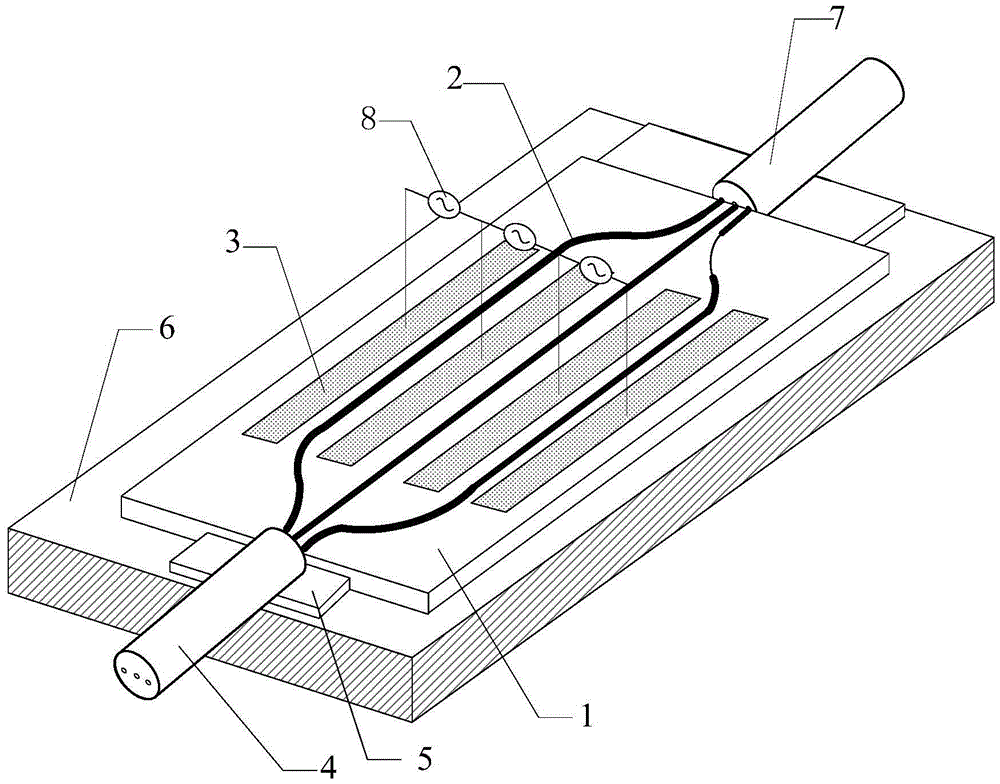
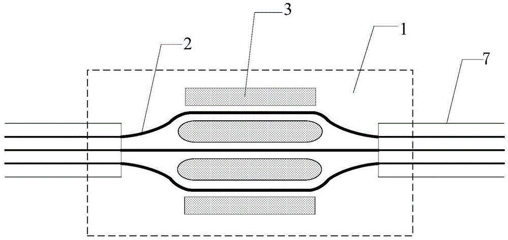
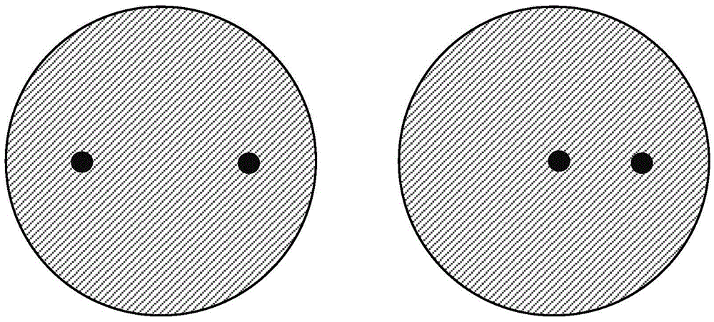
[0024] The invention provides a multi-core optical fiber modulator. The multi-core optical fiber modulator consists of an input end, an electro-optic modulation end, a V-groove, and an output end; the input end is composed of three-core single-mode optical fibers; the electro-optic modulation end is composed of a lithium niobate substrate, four optical waveguides carved by proton exchange, Metal electrode, DC voltage source; metal electrode is divided into cathode and anode; output is a single-mode three-core optical fiber; the multi-core optical fiber modulator can adopt several multi-core optical fibers with different structures, and has a three-channel waveguide device of the modulator , It can realize the discontinuous connection of symmetrical double-core, partial double-core, and planar symmetrical three-core optical fibers. Metal electrodes are embedded in ...


PUM


Abstract

The invention belongs to an optical device part in the field of optical fiber communication, and particularly relates to a multi-core optical fiber modulator. The multi-core optical fiber modulator consists of an input end, an electro-optical modulation end, a V-shaped slot and an output end, wherein the input end consists of a three-core single-mode optical fiber; the electro-optical modulation end consists of a lithium niobate substrate, four light waveguides etched by a proton exchange method, a metal electrode and a direct current voltage source; the metal electrode is divided into a negative electrode and a positive electrode; the output end is a three-core single-mode optical fiber. The input and output optical fibers of the multi-core optical fiber modulator adopt multi-core optical fibers which reduce the cost of an optical fiber and increase the intensity; furthermore, the advantage of measuring a plurality of parameters simultaneously can be realized.

Description

technical field [0001] The invention belongs to the optical device part in the field of optical fiber communication, in particular to a multi-core optical fiber modulator. Background technique [0002] Since entering the new century, the information construction of the society has been developing faster and faster. Among them, optical fiber communication has become the main body of the three pillars in the modern communication network. Optical fiber communication has good anti-electromagnetic interference ability, fast speed, and relatively Small and other advantages are widely used. Optical device is the core part of optical fiber communication. It has the advantages of simple structure, small size, strong anti-interference ability, and easy connection with optical path. With the development of optical fiber communication, the demand for new optical devices is becoming stronger and stronger. [0003] Electro-optic phase modulators are an important class of optical devices...

Claims


Application Information

Patent Timeline
Patent Type & Authority Applications(China)
IPC IPC(8): G02F1/035
CPCG02F1/035
Inventor 苑立波何学兰杨军
Owner HARBIN ENG UNIV
Why Eureka
Try Eureka