Impregnation method for dry capacitance type high-voltage bushing core
A high-voltage bushing, capacitor-type technology, applied in circuits, insulators, electrical components, etc., can solve the problems of difficult to remove air bubbles, low product qualification rate, etc. Effect
- Summary
- Abstract
- Description
- Claims
- Application Information
AI Technical Summary
Problems solved by technology
Method used
Image
Examples
Embodiment 1
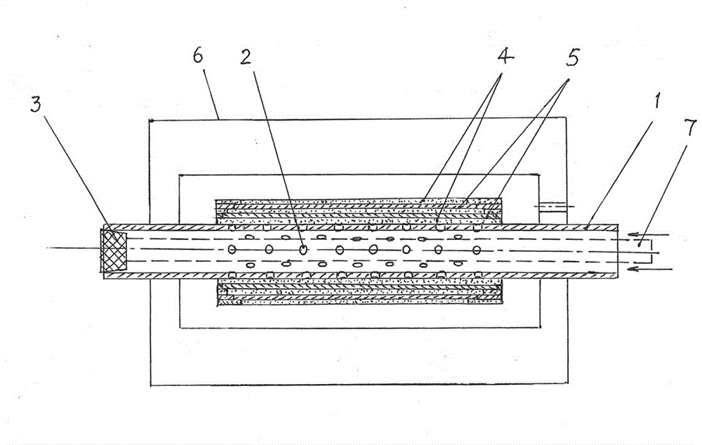
[0025] Such as figure 1 As shown, the dipping method for the core of the dry capacitor type high voltage bushing of the present invention includes the following steps:
[0026] 1. Open a number of distributed through holes 2 on the pipe wall within the range of the capacitive screen on the conductive pipe 1, so that the pipe section forms a mesh pipe section.
[0027] 2. Use the plug 3 to block one end of the conductive tube 1 to form a closed end. The closed end of the conductive tube 1 should be able to withstand more than 2 atmospheric pressures.
[0028] 3. Wrap the outer circumference of the conductive tube 1 with an insulating material to form an insulating layer 4 covering the conductive tube, and then wind the outer circumference of the insulating layer 4 with a conductive material to form a capacitive screen 5 covering the insulating layer, and then on the capacitive screen The outer circumference of 5 is wound with insulating material to form an insulating layer covering t...
Embodiment 2
[0034] Such as figure 1 As shown, the dipping method for the core of the dry capacitor type high voltage bushing of the present invention includes the following steps:
[0035] 1. Open a number of distributed through holes 2 on the pipe wall within the range of the capacitive screen on the conductive pipe 1, so that the pipe section forms a mesh pipe section.
[0036] 2. Insert an inner tube 7 into the conductive tube 1. The length of the inner tube 7 can be greater than the length of the conductive tube 1. There is a sufficient glue gap between the outer wall of the inner tube 7 and the inner wall of the conductive tube 1.
[0037] 3. Close one end (left end) of the conductive tube 1 and the inner tube 7 (the dashed line in the figure) on the same side. The closed end of the conductive tube 1 should be able to withstand more than 3 atmospheric pressures. In addition, the right end of the inner tube 7 should protrude from the open end of the conductive tube 1.
[0038] 4. Wrap the ou...
PUM
 Abstract
Description
Claims
Application Information
 - R&D
- Intellectual Property
- Life Sciences
- Materials
- Tech Scout
- Unparalleled Data Quality
- Higher Quality Content
- 60% Fewer Hallucinations
Browse by: Latest US Patents, China's latest patents, Technical Efficacy Thesaurus, Application Domain, Technology Topic, Popular Technical Reports.
© 2025 PatSnap. All rights reserved.Legal|Privacy policy|Modern Slavery Act Transparency Statement|Sitemap|About US| Contact US: help@patsnap.com

