
Grid of pole plate

A pole plate and plate surface technology, which is applied in the production and processing field of lead-acid batteries, can solve the problems of insufficient electrochemical reaction of surface coating, insufficient battery energy, low utilization rate of active materials, etc., and is conducive to high current discharge. , Guaranteed service life, the effect of increasing the total conductive area

Inactive Publication Date: 2016-06-08
ANHUI YONGHENG STORAGE BATTERY
View PDF4 Cites 2 Cited by
  • Summary
  • Abstract
  • Description
  • Claims
  • Application Information

AI Technical Summary

Problems solved by technology

There are great differences in the grid design of lead-acid batteries in the prior art. The battery grid has the characteristics of many horizontal ribs and few vertical ribs. More resources; the electrochemical reaction of paste on the surface is not sufficient during charging and discharging. When the battery is discharging, due to the small number of vertical ribs and the small total conductive area, the internal resistance of the battery is increased, making the utilization rate of the lead paste extremely low, and the current passes through during charging. The vertical ribs flow to the active material, and the interface of the grid ribs is corroded, and the vertical ribs are easy to break, increasing the internal resistance of the plate, making the battery energy unable to fully exert, and prone to cream dropping and lead paste softening, and accompanied by early capacity The occurrence of attenuation, expansion and creep during the use of the lead paste leads to the end of the life of the active material of the battery and the brittle fracture of the grid leads to the end of the battery life

Method used


Image

  • Grid of pole plate
  • Grid of pole plate
  • Grid of pole plate

Examples


Embodiment Construction

[0022] Referring to the accompanying drawings, through the description of the embodiments, the specific implementation of the present invention, such as the shape, structure, mutual position and connection relationship between the various parts, the function and working principle of each part, and the manufacturing process And the method of operation and use, etc., are described in further detail to help those skilled in the art have a more complete, accurate and in-depth understanding of the inventive concept and technical solutions of the present invention.

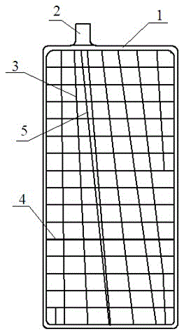
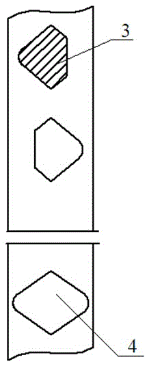
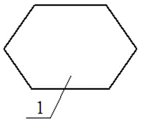
[0023] figure 1 It is a schematic diagram of a plate grid of the present invention; figure 2 for figure 1 Shown is an enlarged view of the transverse rib and oblique rib cross-section of a pole plate grid of the present invention; image 3 for figure 1 Shown is an enlarged view of a large rib cross section of a pole plate grid of the present invention; a pole plate grid of the present invention as shown in the figur...


PUM


Abstract

The invention discloses a grid of pole plate. The grid comprises a pole plate grid body, which comprises a rectangular deck frame, wherein the rectangular deck frame is formed by enclosing a large rib. Non-rectangular net-like grids composed of multiple horizontal ribs and oblique ribs are arranged in the frame; the diagonal positions in the frame are provided with reinforcing ribs; and a position, which is close to the middle part, of the external side of one side of the frame is provided with a rectangular tab. According to the technical scheme mentioned above, the number of vertical ribs of the pole plate grid is increased; the vertical ribs are obliquely arranged, the total conductive area is increased, the battery internal resistance is reduced, the utilization rate of lead paste is guaranteed; moreover, the grid will not be broken off by the expansion or creep deformation of lead paste during the application process, the service life of pole plate grid is guaranteed; the designed structure can improve the conductive performance of grid, is beneficial for large current discharge and fixation of active substances in grid, and disperses the expansion stress of lead paste, thus expansion and creep deformation of lead paste are avoided during the application process, the moulding of grid skeleton is enhanced; the force bearing strength of six surfaces of grid is reinforced, and the comprehensive performance of grid is improved.

Description

technical field [0001] The invention belongs to the field of production and processing of lead-acid batteries, and more specifically, the invention relates to a pole plate grid. Background technique [0002] The lead-acid battery grid supports the active material of the lead-acid battery. The grid is the carrier of the active material and the channel for the battery to charge and discharge the current. The design of the grid structure directly determines the difference in battery performance. There are great differences in the grid design of lead-acid batteries in the prior art. The battery grid has the characteristics of many horizontal ribs and few vertical ribs. More resources; the electrochemical reaction of paste on the surface is not sufficient during charging and discharging. When the battery is discharging, due to the small number of vertical ribs and the small total conductive area, the internal resistance of the battery is increased, making the utilization rate of...

Claims


Application Information

Patent Timeline
IPC IPC(8): H01M4/73H01M2/28H01M50/541
CPCH01M4/73H01M50/541Y02E60/10
Inventor 张泽波郑晓飞吴荣良
Owner ANHUI YONGHENG STORAGE BATTERY
Learn More