A method for testing electrical parameters applicable to high-efficiency photovoltaic cell components

A technology of photovoltaic cells and electrical parameters, applied in the monitoring of photovoltaic systems, photovoltaic power generation, photovoltaic modules, etc., can solve problems such as increasing test man-hours and reducing production efficiency, and achieve the effect of increasing the value of components and improving accuracy

Active Publication Date: 2017-11-28
HEFEI & SOLAR TECH
View PDF4 Cites 0 Cited by
  • Summary
  • Abstract
  • Description
  • Claims
  • Application Information

AI Technical Summary

Problems solved by technology

[0004] In order to reduce the influence of the capacitive effect, some manufacturers adopt the method of reducing the scanning rate and prolonging the scanning time to reduce the influence of the charging current. For example, the test cycle is changed from one flash to multiple flashes. , the rate of change of the voltage gradually decreases, so this method will inevitably increase the testing man-hours and reduce the production efficiency

Method used


Image

  • A method for testing electrical parameters applicable to high-efficiency photovoltaic cell components
  • A method for testing electrical parameters applicable to high-efficiency photovoltaic cell components
  • A method for testing electrical parameters applicable to high-efficiency photovoltaic cell components

Examples


Embodiment 1

[0020] see figure 1 , the present invention can be applied to the electrical parameter testing method of high-efficiency photovoltaic cell components, including:

[0021] Step 1. Apply a linear scanning voltage to both ends of the tested photovoltaic cell assembly within the preset test time T0, measure the operating current of the tested photovoltaic cell assembly under this test condition, and calculate the tested photovoltaic cell assembly. The maximum power point under test conditions to obtain the maximum power point voltage value Ump;

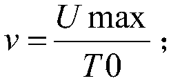
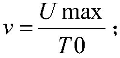
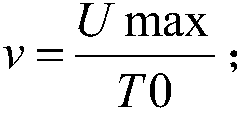
[0022] Among them, the change curve of the linear scanning voltage within the test time T0 is the linear voltage curve L1, and the linear voltage curve L1 rises linearly from 0V to the maximum scanning voltage Umax of the photovoltaic cell module under test within the test time T0, that is, the linear voltage curve The boost rate of L1 is The preset test time T0 depends on the performance of the equipment that applies the scanning volt...

Embodiment 2

[0033] The test method of the second embodiment of the present invention is basically the same as that of the first embodiment, and their difference is that in the second embodiment, the scanning voltage value at the end of the decapacitating phase L22, that is, the scanning voltage value at the beginning of the termination phase L23 is greater than that calculated in step one. The obtained maximum power point voltage value Ump is 2V larger.

Embodiment 3

[0035] The test method of the second embodiment of the present invention is basically the same as that of the first embodiment, and their difference is that in the second embodiment, the scanning voltage value at the end of the decapacitating phase L22, that is, the scanning voltage value at the beginning of the termination phase L23 is greater than that calculated in step one. The obtained maximum power point voltage value Ump is 3V larger.


PUM


Abstract

The invention discloses an electrical parameter test method capable of being applicable to a high-efficiency photovoltaic cell module. The electrical parameter test method capable of being applicable to the high-efficiency photovoltaic cell module comprises the following steps: firstly applying linear scanning voltage to two ends of a tested photovoltaic cell module within preset test time, measuring working current of the tested photovoltaic cell module under the test condition, and calculating the maximum power point of thetested photovoltaic cell module under the test condition, so that voltage value at the maximum power point is obtained; and secondly, applying non-linear scanning voltage to the two ends of the tested photovoltaic cell module in the step one within test time the same as the step one, measuring working current of the test photovoltaic cell module under the test condition, and taking a test result of the step two as an electrical parameter test result of the tested photovoltaic cell module. The electrical parameter test method capable of being applicable to the high-efficiency photovoltaic cell module has the advantages that influence of charging current of the photovoltaic cell module, especially the high-efficiency photovoltaic cell module, namely capacitance effect on test is effectively reduced, accuracy of electrical parameter test is improved, and time cost of test can not be increased.

Description

technical field [0001] The invention relates to an electrical parameter testing method applicable to high-efficiency photovoltaic battery components. Background technique [0002] With the increasingly fierce competition in the photovoltaic industry, more and more attention has been paid to reducing the cost of photovoltaic systems. Improving battery efficiency has become a priority for many photovoltaic companies. For example, PERC (passivated emitter back contact) cells, HIT (heterojunction) cells, etc., the conversion efficiency can reach more than 20%. The high-efficiency battery has a high open circuit voltage (Voc), and the capacitance effect of the battery and its packaged components is relatively large. The electrical parameter testing process of the components is generally to apply a scanning voltage across the battery components and test the response curve of the current. The changing voltage causes the capacitor to charge and discharge. The charging and discha...

Claims


Application Information

Patent Timeline
Patent Type & Authority Patents(China)
IPC IPC(8): H02S50/10
CPCH02S50/10Y02E10/50
Inventor 崔廷朱生宾李陶谢伟李奎蒋明强王凌祥
Owner HEFEI & SOLAR TECH
Why Eureka
Try Eureka