Automatic gain control method and system for receiver

An automatic gain control and gain control technology, applied in transmission systems, electrical components, etc., can solve the problems of signal instability, limited range and influence of radio frequency signal automatic gain control, and achieve the effect of ensuring linearity and improving the range of automatic gain control

Active Publication Date: 2016-06-08
HUNAN KEAYSHARE COMM TECH CO LTD
View PDF5 Cites 4 Cited by
  • Summary
  • Abstract
  • Description
  • Claims
  • Application Information

AI Technical Summary

Problems solved by technology

[0004] These methods mainly include two types, one is to add an attenuator at the front end of the receiver link, but if only one attenuator is added, the automatic gain control range of the radio frequency signal is very limited, and it is not suitable for long-distance data transmission. transmission
[0005] The other is to add two or more stages of attenuators. This method can expand the range of automatic gain control. However, since the single-chip microcomputer cannot control the multi-stage attenuators at the same time, it is easy to cause adverse effects on the signals of the links of all levels of the entire receiver. stable impact

Method used


Image

  • Automatic gain control method and system for receiver
  • Automatic gain control method and system for receiver
  • Automatic gain control method and system for receiver

Examples


Embodiment 1

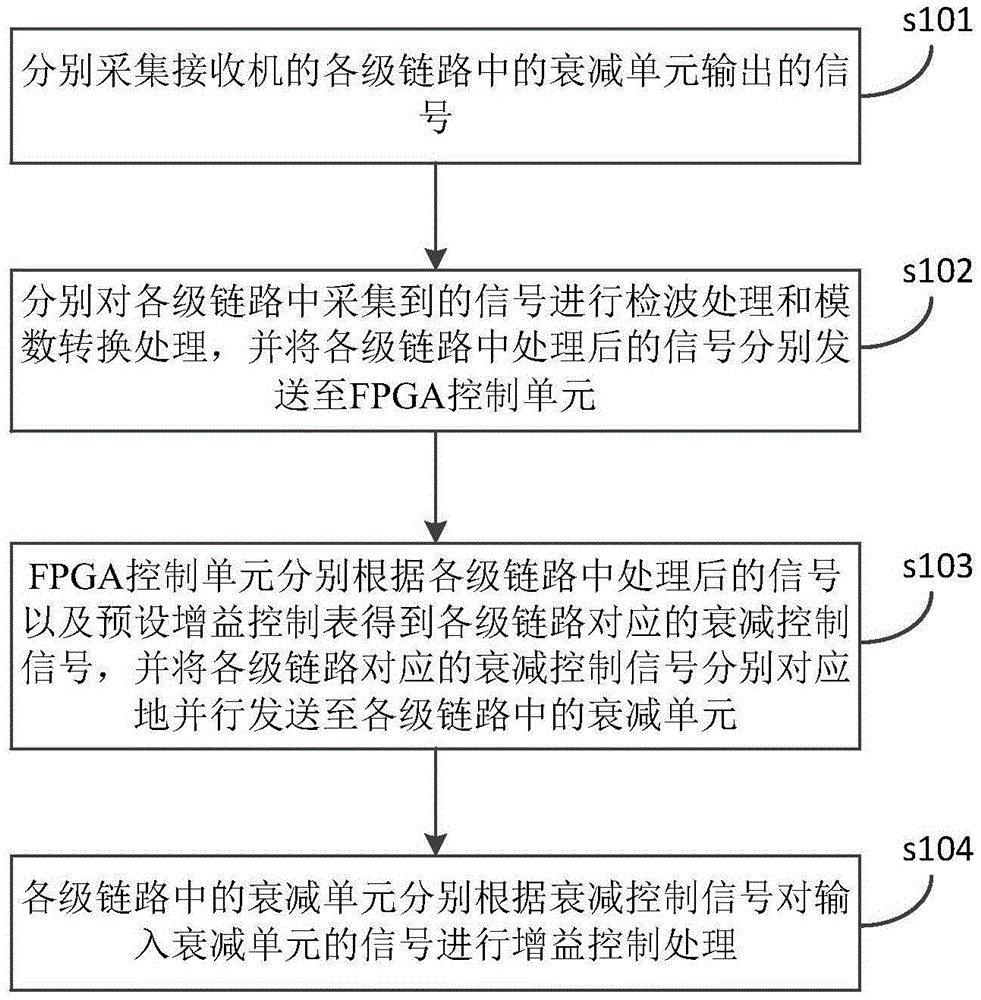
[0038] The present invention provides a receiver automatic gain control method, see figure 1 As shown, figure 1 It is a flowchart of the process of a receiver automatic gain control method provided by the present invention; the method includes:

[0039] Step s101: Collect the signals output by the attenuation units in each level of the link of the receiver respectively;

[0040] Step s102: Perform detection processing and analog-to-digital conversion processing on the signals collected in the links at all levels, and send the processed signals in the links at all levels to FPGA (Field-ProgrammableGateArray) for control. unit;

[0041] Step s103: The FPGA control unit obtains the attenuation control signal corresponding to each level of link according to the processed signal in each level of link and the preset gain control table, and sends the attenuation control signal corresponding to each level of link respectively in parallel To the attenuation unit in the link at all levels;

[...

Embodiment 2

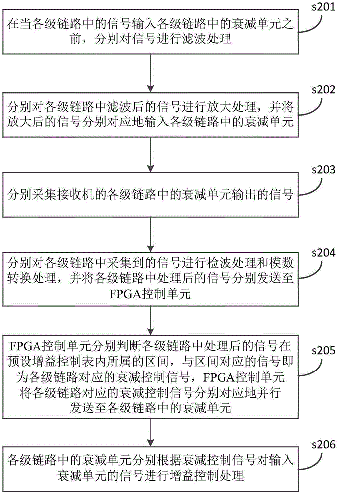
[0045] The present invention also provides another receiver automatic gain control method, see figure 2 As shown, figure 2 It is a flow chart of the process of another receiver automatic gain control method provided by the present invention; the method includes:

[0046] Step s201: before the signals in the links at all levels are input to the attenuation units in the links at all levels, filter the signals respectively;

[0047] Among them, the receiver here may be a receiver using double conversion. In this case, the various levels of the receiver's links are a radio frequency link, a high intermediate frequency link, and a low intermediate frequency link.


PUM


Abstract

The invention discloses an automatic gain control method for a receiver. The automatic gain control method comprises the steps: a signal output by an attenuation unit in each link of the receiver is acquired respectively; the acquired signal in each link is subjected to demodulation processing and analog to digital conversion processing, and the processed signal in each link is sent to an FPGA control unit; the FPGA control unit obtains an attenuation control signal corresponding to each link according to the processed signal in each link and a preset gain control table, and the attenuation control signals corresponding to all the links are correspondingly sent to the attenuation units in the all links in a parallel manner respectively; and the attenuation unit in each link performs gain control processing on a signal input into the attenuation unit according to the corresponding attenuation control signal respectively. According to the method, the attenuation units in the all links are controlled in a parallel manner, so as to avoid chaos of control of all the links; and in addition, an automatic gain control range of signals in the receiver is greatly widened. The invention further discloses an automatic gain control system for the receiver.

Description

Technical field [0001] The invention relates to the field of automatic gain control, in particular to a receiver automatic gain control method. The invention also relates to a receiver automatic gain control system. Background technique [0002] As the current requirements for communication rates are getting higher and higher, the channel bandwidth is getting wider, and the linearity requirements for the receiver channel are getting higher and higher. Therefore, certain requirements are put forward for the receiver link, and the receiver (such as The receiver with double frequency conversion can automatically control the gain, so that the power output of the radio frequency signal can be maintained in a stable range to achieve the purpose of maintaining the maximum signal-to-noise ratio of the radio frequency signal. And for the receiver, if it wants to realize normal communication between the receiver and the transmitter at various distances, the receiver itself is also require...

Claims


Application Information

Patent Timeline
Patent Type & Authority Applications(China)
IPC IPC(8): H04B1/12
CPCH04B1/123
Inventor 王德刚李尚立
Owner HUNAN KEAYSHARE COMM TECH CO LTD
Why Eureka
Try Eureka