
Device and method for manufacturing integrated rotary cutting tool

A cutting tool and manufacturing equipment technology, applied in the field of workpiece grinding, can solve the problems of low efficiency of axial feeding, large space occupied by horizontal grinding, inconvenient detection of rough grinding accuracy, etc., to reduce manual transfer of workpieces , Improve grinding efficiency and save the area occupied by equipment

Active Publication Date: 2016-06-15
SHENZHEN JINZHOU PRECISION TECH
View PDF5 Cites 9 Cited by
  • Summary
  • Abstract
  • Description
  • Claims
  • Application Information

AI Technical Summary

Problems solved by technology

[0002] Generally, the grinding of cylindrical workpieces, such as the grinding of micro drills, generally adopts the integrated processing equipment for rough and fine grinding of horizontal clamping workpieces, that is, the workpieces are placed horizontally and ground, and elastic chucks are used to clamp the workpieces. The workpiece is driven to rotate, and then the clamping method is positioned by the V-shaped block; the grinding wheel is fed in the axial direction of the workpiece; the rough grinding wheel and the fine grinding wheel are used to grind the adjacent parts of the workpiece edge at the same time; however, this The elastic collet and the V-shaped block will act on the handle of the workpiece at the same time, forming over-positioning. When the workpiece rotates, the axis will drift, and the coaxiality error between the blade diameter and the handle will be large after machining; and the axial feed method Low efficiency; at the same time, because the rough grinding wheel and the fine grinding wheel act on the workpiece at the same time, the accuracy of the rough grinding is not easy to detect, and the horizontal grinding takes up a lot of space and the equipment is bulky; moreover, in the prior art, the feeding and discharging All adopt the tray loading method. Before feeding, an additional swinging process is required to place the workpiece into the tray, which increases the process and reduces production efficiency.

Method used


Image

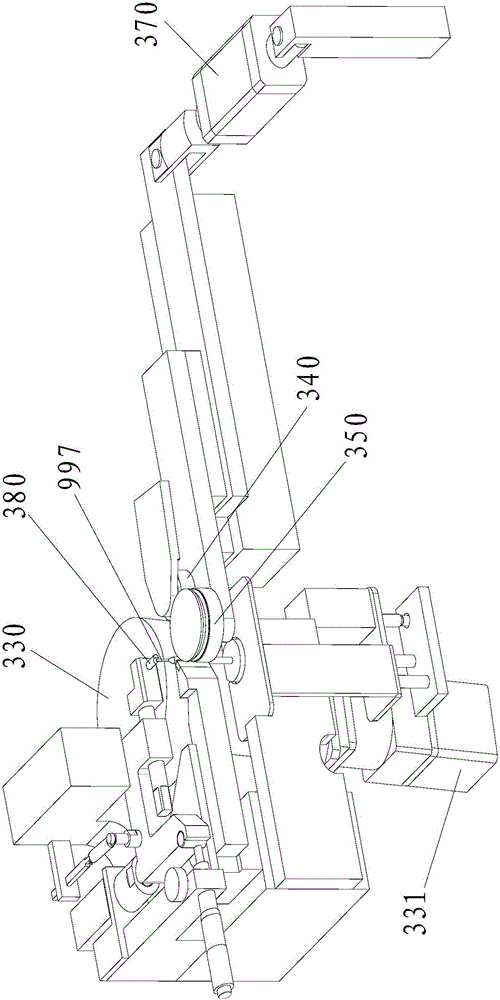
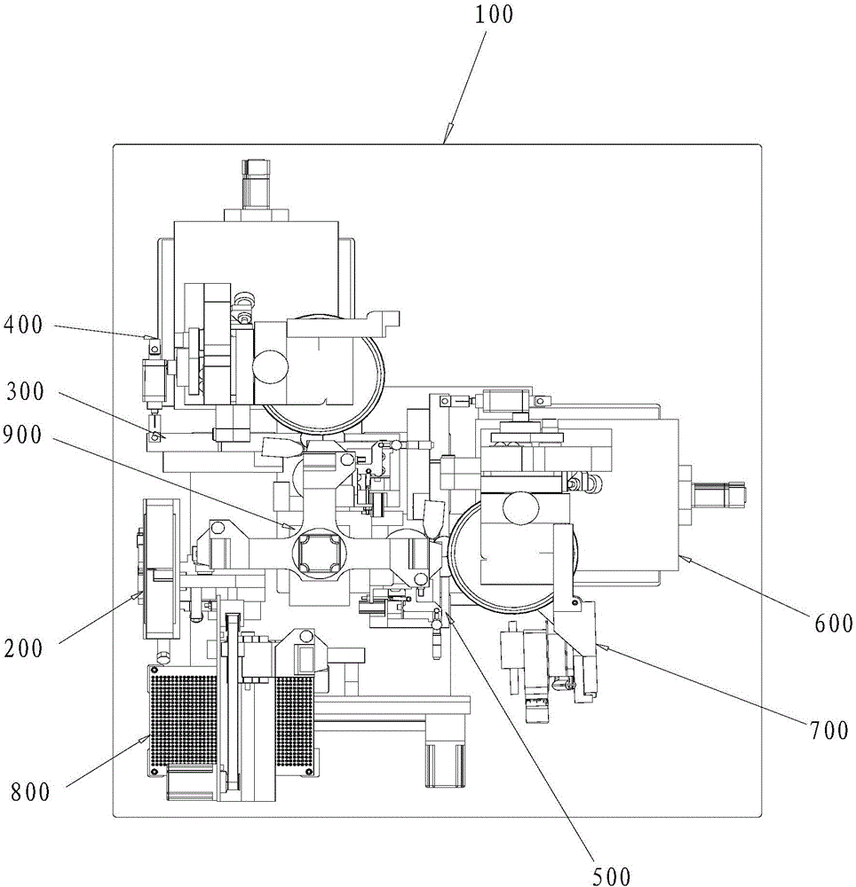
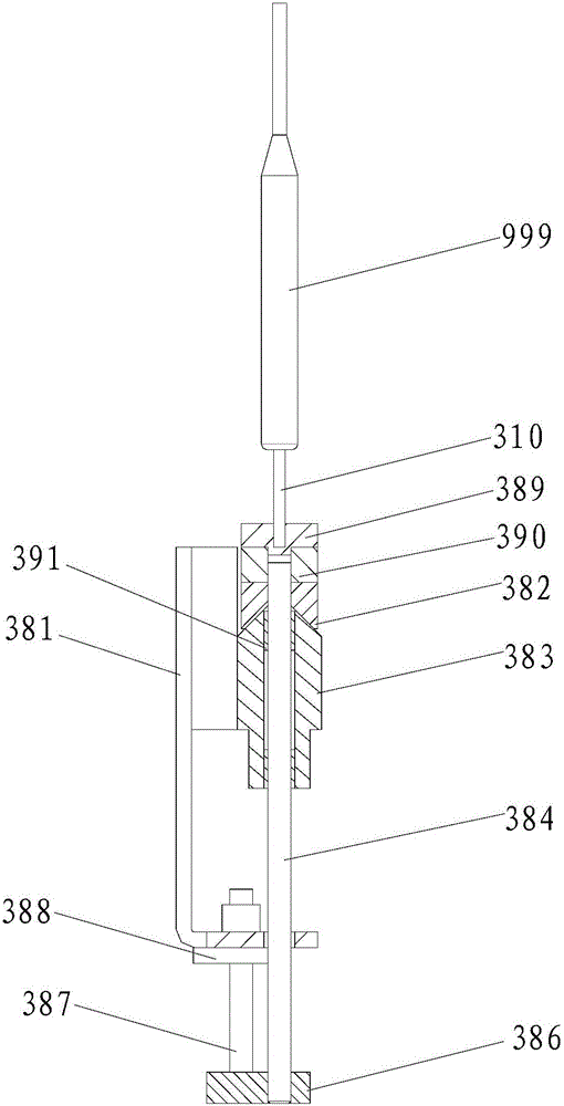
  • Device and method for manufacturing integrated rotary cutting tool
  • Device and method for manufacturing integrated rotary cutting tool
  • Device and method for manufacturing integrated rotary cutting tool

Examples


Embodiment Construction

[0037] In order to make the object, technical solution and advantages of the present invention clearer, the present invention will be further described in detail below in conjunction with the accompanying drawings and embodiments. It should be understood that the specific embodiments described here are only used to explain the present invention, not to limit the present invention.

[0038] It should be noted that when an element is referred to as being “fixed on” or “disposed on” another element, it may be directly on the other element or there may be an intervening element at the same time. When an element is referred to as being "connected to" another element, it can be directly connected to the other element or intervening elements may also be present.

[0039] It should also be noted that the orientation terms such as left, right, up, and down in the embodiments of the present invention are only relative concepts or refer to the normal use state of the product, and should ...


PUM


Abstract

The invention relates to the field of workpiece grinding, in particular to the technical field of microbits for PCB machining, and discloses a device and method for manufacturing an integrated rotary cutting tool. The device for manufacturing the integrated rotary cutting tool comprises a workpiece transfer device, a machine body, a feeding device, a grinding device and a discharging device. The grinding device comprises a coarse grinding device body used for carrying out primary grinding on vertically-arranged workpieces and a fine grinding device body used for carrying out secondary grinding on the vertically-arranged workpieces. The device for manufacturing the integrated rotary cutting tool is adopted in the method for manufacturing the rotary cutting tool. According to the device and method for manufacturing the integrated rotary cutting tool, the device is compact in structure, high in machining efficiency and precision and low in cost, the maximum value, the minimum value and the average value of the roundness of the microbits and the maximum value, the minimum value and the average value of the concentricity of the microbits are closer to the standard values, the capability index of the roundness in the stabilization process can be 2.0242, the capability index of the concentricity in the stabilization process can be 2.6657, and the machining precision is remarkably improved.

Description

technical field [0001] The invention belongs to the field of workpiece grinding, and in particular relates to an integrated rotary cutting tool manufacturing equipment and a manufacturing method. Background technique [0002] Generally, the grinding of cylindrical workpieces, such as the grinding of micro drills, generally adopts the integrated processing equipment for rough and fine grinding of horizontal clamping workpieces, that is, the workpieces are placed horizontally and ground, and elastic chucks are used to clamp the workpieces. The workpiece is driven to rotate, and then the clamping method is positioned by the V-shaped block; the grinding wheel is fed in the axial direction of the workpiece; the rough grinding wheel and the fine grinding wheel are used to grind the adjacent parts of the workpiece edge at the same time; however, this The elastic collet and the V-shaped block will act on the handle of the workpiece at the same time, forming over-positioning. When th...

Claims


Application Information

Patent Timeline
IPC IPC(8): B24B41/00B24B27/00B24B3/24B24B41/06B24B47/20B24B47/12B24B53/06
CPCB24B3/24B24B27/0023B24B27/0046B24B27/0076B24B41/005B24B41/06B24B47/12B24B47/20B24B53/06B24B53/075B24B27/0084B24B47/22B24B51/00
Inventor 韩庆红朱建刘军力
Owner SHENZHEN JINZHOU PRECISION TECH
Learn More