Calibration system and method of robot
A calibration system and robot technology, applied in manipulators, program-controlled manipulators, manufacturing tools, etc., can solve the problems of expensive equipment, complicated installation and operation, and low positioning accuracy
- Summary
- Abstract
- Description
- Claims
- Application Information
AI Technical Summary
Problems solved by technology
Method used
Image
Examples
Embodiment 1
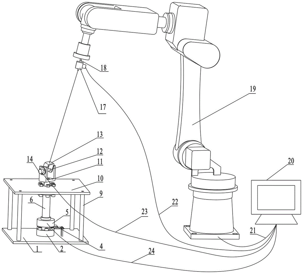
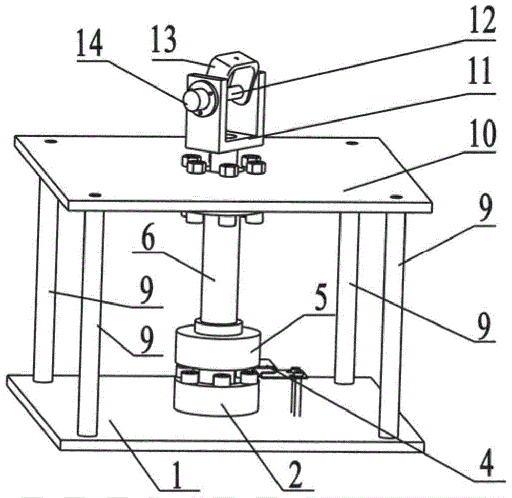
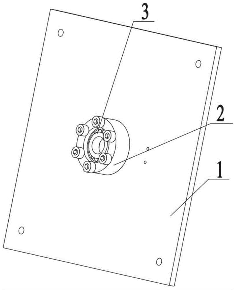
[0056] Embodiment 1: as Figure 1-6 As shown, a robot calibration system includes a calibration device, a robot 19, a computer 20, a robot cable 21, and a calibration device cable;
[0057] The calibration device is connected and communicated with the computer 20 by the calibration device cable, and the robot 19 is connected and communicated with the computer 20 by the robot cable 21; the data of the calibration device and the joint rotation angle of the robot 19 are collected by the computer 20, and the calibration device is obtained according to two consecutive acquisitions. The data of the robot 19 is used to calculate the distance between two points in space at the end of the robot 19; the data of the calibration device includes the length of the wire of the wire sensor 17, the angle of the angle sensor I5, and the angle of the angle sensor II14.
[0058] The calibration device includes a lower base plate 1, a bearing housing I2, a tapered roller bearing I3, a blocking pla...
Embodiment 2
[0094] Embodiment 2: as Figure 1-6 As shown, a robot calibration system includes a calibration device, a robot 19, a computer 20, a robot cable 21, and a calibration device cable;
[0095] The calibration device is connected and communicated with the computer 20 by the calibration device cable, and the robot 19 is connected and communicated with the computer 20 by the robot cable 21; the data of the calibration device and the joint rotation angle of the robot 19 are collected by the computer 20, and the calibration device is obtained according to two consecutive acquisitions. The data of the robot 19 is used to calculate the distance between two points in space at the end of the robot 19; the data of the calibration device includes the length of the wire of the wire sensor 17, the angle of the angle sensor I5, and the angle of the angle sensor II14.
[0096] The calibration device includes a lower base plate 1, a bearing housing I2, a tapered roller bearing I3, a blocking pla...
Embodiment 3
[0130] Embodiment 3: as Figure 1-6 As shown, a robot calibration system includes a calibration device, a robot 19, a computer 20, a robot cable 21, and a calibration device cable;
[0131] The calibration device is connected and communicated with the computer 20 by the calibration device cable, and the robot 19 is connected and communicated with the computer 20 by the robot cable 21; the data of the calibration device and the joint rotation angle of the robot 19 are collected by the computer 20, and the calibration device is obtained according to two consecutive acquisitions. The data of the robot 19 is used to calculate the distance between two points in space at the end of the robot 19; the data of the calibration device includes the length of the wire of the wire sensor 17, the angle of the angle sensor I5, and the angle of the angle sensor II14.
[0132] The calibration device cable includes a pull wire sensor cable 22, an angle sensor cable II24, and an angle sensor cabl...
PUM
 Abstract
Description
Claims
Application Information
 - R&D
- Intellectual Property
- Life Sciences
- Materials
- Tech Scout
- Unparalleled Data Quality
- Higher Quality Content
- 60% Fewer Hallucinations
Browse by: Latest US Patents, China's latest patents, Technical Efficacy Thesaurus, Application Domain, Technology Topic, Popular Technical Reports.
© 2025 PatSnap. All rights reserved.Legal|Privacy policy|Modern Slavery Act Transparency Statement|Sitemap|About US| Contact US: help@patsnap.com


