Electric power overhaul equipment lifting device

A lifting device and power maintenance technology, applied in the direction of lifting equipment safety device, lifting device, lifting frame, etc., can solve the problems of large occupied space, fixed equipment volume, inability to shrink, etc., to achieve convenient storage and movement, safe and reliable structure , the effect of reducing the space occupied

Active Publication Date: 2016-06-15
STATE GRID CORP OF CHINA +1
View PDF7 Cites 19 Cited by
  • Summary
  • Abstract
  • Description
  • Claims
  • Application Information

AI Technical Summary

Problems solved by technology

The existing lifting equipment has a simple structure, mainly using hoisting machinery to realize the lifting of the equipment, which takes up a lot of space, and the overall equipment volume is fixed and cannot be shrunk. When moving and storing, a large amount of space is required for operation. In the process of moving, there are often super high phenomena above it

Method used


Image

  • Electric power overhaul equipment lifting device
  • Electric power overhaul equipment lifting device

Examples


Embodiment 1

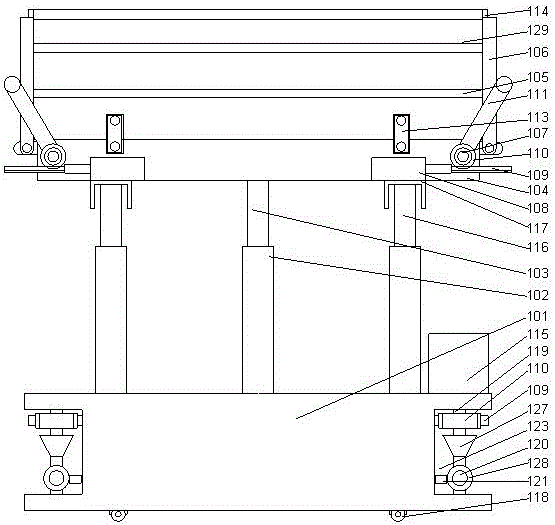
[0027] Such as figure 1 , 2 As shown, a lifting device for electric power maintenance equipment includes a base 101 and a hydraulic lifting assembly arranged above the base, a lifting platform 104 is arranged above the base, and the lifting platform is close to two mutually parallel edge parts A fixed frame 105 is respectively arranged above, and a movable frame 106 is arranged on the other two mutually parallel side walls of the lifting platform, and the moving frame is hinged on the side wall of the lifting platform. Compressed airbags are respectively arranged on the inner end surfaces of the fixed frame and the movable frame;

[0028] Two rotating shafts 107 are arranged on the side wall of the lifting platform, and the moving frames are respectively sleeved on the rotating shafts, and a first hydraulic cylinder 108 is arranged on the lower end surface of the lifting platform. A rack 109 is provided on the telescopic rod of the first hydraulic cylinder, a gear 110 is pro...

Embodiment 2

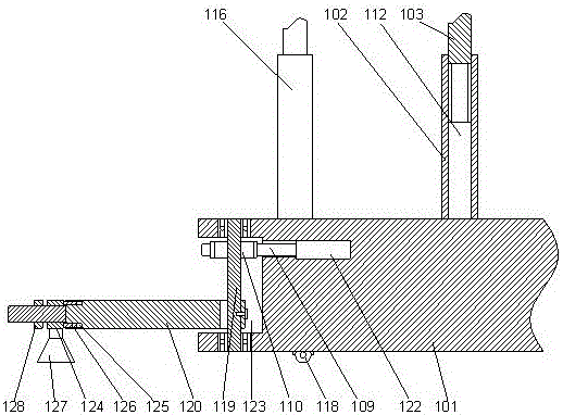
[0034]This embodiment is based on Embodiment 1. In this embodiment, in order to make the lifting platform more stable, preferably, a channel steel is provided on the lower end surface of the lifting platform, and a second Three hydraulic cylinders 116, the telescopic rod of the third hydraulic cylinder can be clamped in the channel steel, and the third hydraulic cylinder is connected with the controller through a line. The third hydraulic cylinder can be arranged on both sides of the hydraulic lifting assembly to make the overall structure more stable. At the same time, an inclined support reinforcement structure can be arranged outside the third hydraulic cylinder to facilitate the stability of the third hydraulic cylinder.

[0035] In order to facilitate the movement of the whole structure, in this embodiment, preferably, a roller 118 is provided under the base.

[0036] In order to increase the stress-bearing area of ​​the base and improve the stability of the overall struc...


PUM


Abstract

The invention discloses an electric power overhaul equipment lifting device which comprises a base and a hydraulic lifting assembly arranged on the base. A lifting platform is arranged over the base, fixed frames are arranged over the positions, close to the two parallel edges, of the lifting platform respectively, moving frames are arranged on the other two parallel side walls of the lifting platform, and the moving frames are hinged to the side walls of the lifting platform; the side walls of the lifting platform are provided with two rotating shafts, the rotating shafts are sleeved with the moving frames respectively, the lower end face of the lifting platform is provided with a first hydraulic cylinder, the rotating shafts are provided with pressing rods, and the two ends of each pressing rod are bent by 90 degrees towards the same side. According to the electric power overhaul equipment lifting device, by adopting the fixed frames and the moving frames which are hinged to the lifting platform, the fixed frames and the moving frames can be conveniently combined to form a guard bar structure in use and can be contracted and folded on the lifting platform when the fixed frames and the moving frames are not used, and the equipment is conveniently stored.

Description

technical field [0001] The invention relates to a lifting device for electric power maintenance equipment. Background technique [0002] During electric power construction, the staff need to use lifting equipment to push the maintenance personnel and equipment to the designated height for easy operation. The existing lifting equipment has a simple structure, mainly using hoisting machinery to realize the lifting of the equipment, which takes up a lot of space, and the overall equipment volume is fixed and cannot be shrunk. When moving and storing, a large amount of space is required for operation. In the process of moving, there are often super high phenomena above it. Contents of the invention [0003] The purpose of the present invention is to provide a lifting device for electric power maintenance equipment, which can improve the problems existing in the prior art. By adopting a fixed frame and a movable frame hinged with the lifting platform, it is convenient to combi...

Claims


Application Information

Patent Timeline
Patent Type & Authority Applications(China)
IPC IPC(8): B66F11/04B66F17/00
CPCB66F7/16B66F7/28B66F11/04B66F17/006
Inventor 陈键国际昌
Owner STATE GRID CORP OF CHINA
Why Eureka
Try Eureka