Alumina continuous feeding equipment

An alumina and equipment technology, applied in the field of electrolysis, can solve the problems of alumina concentration fluctuations, increased energy consumption, large fluctuations in tank heat balance, etc., to reduce temperature and alumina concentration fluctuations, reduce the formation of furnace bottom deposits, and increase current efficiency effect

Active Publication Date: 2017-11-24
SNTO TECH GRP
View PDF5 Cites 0 Cited by
  • Summary
  • Abstract
  • Description
  • Claims
  • Application Information

AI Technical Summary

Problems solved by technology

The deficiencies of the related technology are: (1) This blanking method is intermittent blanking, the concentration of alumina fluctuates significantly, the concentration before blanking is low, the concentration after blanking is high, and the heat balance of the tank fluctuates greatly, which affects the stability and stability of the electrolytic cell. current efficiency; (2) A large amount of alumina is fed into a single batch of point feeding method, and the current low superheat process route makes the dissolution process of alumina more difficult, and the undissolved alumina sinks into the aluminum liquid, which causes the lower A large amount of alumina precipitates accumulate in the aluminum liquid layer directly below the feed port, and the precipitate covers the bottom of the furnace with the flow of aluminum liquid, causing an increase in the pressure drop at the bottom of the furnace and increasing energy consumption. In severe cases, it can lead to deformed furnace and affect the service life of the tank; (3 ) A large amount of alumina that is fed in a single time is accelerated on the blanking slant plate, and scattered around after hitting the shelling head at the outlet, the actual material entering the tank is reduced, which is easy to cause the effect

Method used


Image

  • Alumina continuous feeding equipment
  • Alumina continuous feeding equipment
  • Alumina continuous feeding equipment

Examples


Embodiment Construction

[0021] The present invention will be further described below in conjunction with the accompanying drawings and embodiments.

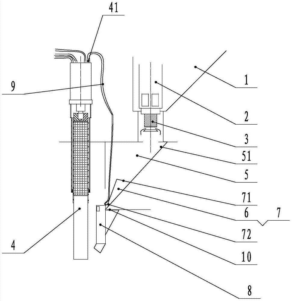
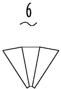
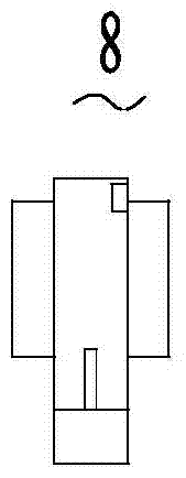
[0022] see Figure 1-Figure 5 , a continuous alumina blanking equipment, comprising: a feeder box 1 for holding alumina powder, a feeder cylinder 2 arranged at the bottom of the feeder box 1, arranged below the feeder cylinder 2 and connected to the feeder cylinder 2 The constant container 3; the alumina continuous feeding device also includes a shelling head 4 for breaking the surface of the material in the electrolytic cell (not shown), and a shelling head 4 and the constant container 3 are provided for alumina from The fixed container 3 enters the material passing frame 5 of the electrolytic cell (not shown), and the material passing frame 5 includes a sloping plate 51, wherein the alumina continuous blanking equipment also includes a buffer 6 arranged in the material passing frame 5, buffering The device 6 and the inclined plate 51 together form a ...


PUM


Abstract

The invention discloses continuous aluminum oxide feeding equipment which comprises a material box, a feeding air cylinder, a fixed container, a crust breaking head, a material passing frame, an oblique plate, a buffer and a feeding pipe. The feeding pipe is led to the bottom of the crust breaking head. The continuous aluminum oxide feeding equipment further comprises an air pipe which is arranged at a buffer outlet and used for blowing air to the buffer outlet. Compared with the prior art, the continuous aluminum oxide feeding equipment has the beneficial effects that (1) aluminum oxide is made to enter an electrolyte slowly, and the temperature fluctuation of an electrolytic cell and the concentration fluctuation of the aluminum oxide are reduced, so that the current efficiency is improved, and energy consumption is reduced; (2) the aluminum oxide is made to have enough time to be melted into the electrolyte, so that sediment at the furnace bottom is reduced, the pressure drop at the furnace bottom is reduced, and energy consumption is reduced; (3) the aluminum oxide is made to enter the electrolyte slowly through a pipeline, and the crust breaking head is prevented from being impacted so that the aluminum oxide can be prevented from being dispersed, the actual amount of materials entering the electrolytic cell is increased, and the effect coefficient is decreased; and (4) large particles in the aluminum oxide are blown away through the gas reverse blowing principle, so that blockage is eliminated, and the hole blockage phenomenon can be effectively prevented.

Description

【Technical field】 [0001] The invention relates to the technical field of electrolysis, in particular to an alumina continuous feeding equipment. 【Background technique】 [0002] In the preparation of electrolytic aluminum, it is necessary to use alumina continuous feeding equipment to add alumina powder into the electrolytic cell. In the related art, a timed constant volume feeder is used for intermittent feeding. This alumina continuous feeding equipment includes: a feeder box for holding alumina powder, a feeder cylinder arranged at the bottom of the feeder box, arranged below the feeder cylinder and connected with the feeder A fixed container connected to the cylinder, the alumina continuous feeding device also includes a shelling head for breaking the surface of the material in the electrolytic cell, and a fixed container for alumina is arranged between the shelling head and the fixed container. Enter the material passing frame of the electrolyzer. The deficiencies of t...

Claims


Application Information

Patent Timeline
Patent Type & Authority Patents(China)
IPC IPC(8): C25C3/14
CPCC25C3/14
Inventor 章宣洪波敬叶灵李泉
Owner SNTO TECH GRP
Why Eureka
Try Eureka