Oil cooling turbine moving blade

A moving blade and turbine technology, which is applied to the supporting elements of the blade, the turbine/propulsion fuel delivery system, the fuel flow passage of the turbine/propulsion device, etc., can solve the problem of limited use of air turbines, and achieve the effect of reducing weight

Active Publication Date: 2016-06-15
HARBIN INST OF TECH
View PDF4 Cites 10 Cited by
  • Summary
  • Abstract
  • Description
  • Claims
  • Application Information

AI Technical Summary

Problems solved by technology

Designing an air turbine with oil-cooled blades has become a solution to the limited use of air turbines under hypersonic flight conditions

Method used


Image

  • Oil cooling turbine moving blade
  • Oil cooling turbine moving blade
  • Oil cooling turbine moving blade

Examples


specific Embodiment approach 1

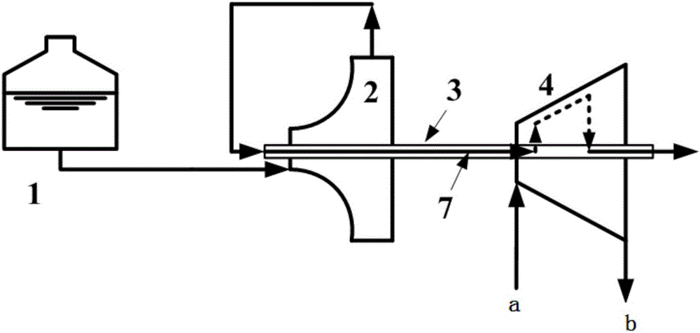
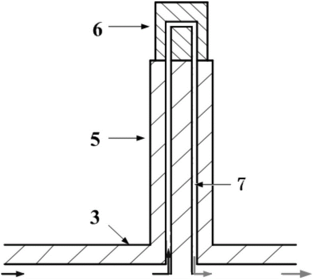
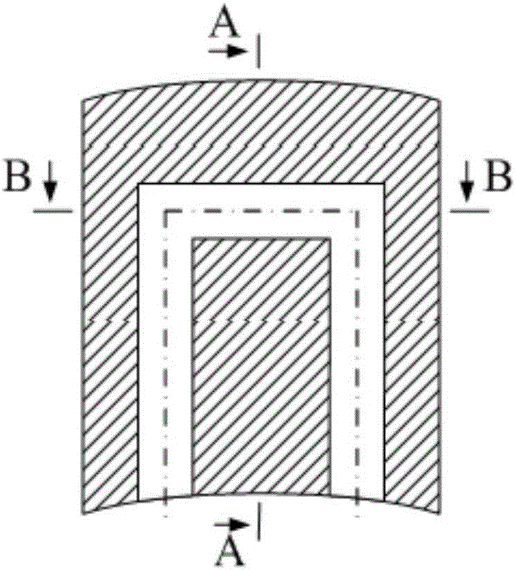
[0019] Embodiment 1: In this embodiment, an oil-cooled turbine moving blade includes a fuel tank 1, a fuel pump 2, a hollow shaft 3, and an air turbine 4. The hollow tubular structure inside the hollow shaft 3 is a cooling channel 7, and the rotor part of the air turbine 4 It is composed of a disc 5 and blades 6. The cooling channel 7 is distributed inside the disc 5 and the vanes 6. The outlet of the fuel tank 1 communicates with the inlet of the fuel pump 2. The fuel pump 2 and the air turbine 4 are installed on the hollow shaft 3 in turn. The fuel pump 2. The outlet communicates with the inlet of the cooling channel 7 in the hollow shaft 3, and the end of the hollow shaft 3 leads into the combustion chamber.

[0020] In this embodiment, the fuel tank 1 is used to store fuel, the fuel pump 2 is used to pressurize the fuel, and the hollow shaft 3 has dual functions, firstly used to fix the fuel pump 2 and the air turbine 4, and secondly used to connect the cooling channel 7 be...

specific Embodiment approach 2

[0021] Embodiment 2: The difference between this embodiment and Embodiment 1 is that the oil-cooled turbine rotor blades are cooled by fuel. Others are the same as in the first embodiment.

specific Embodiment approach 3

[0022] Embodiment 3: This embodiment differs from Embodiment 1 or Embodiment 2 in that: the fuel pump 2 and the air turbine 4 use the hollow shaft 3 as the connecting shaft. Others are the same as in the first or second embodiment.

[0023] The positions of the cooling passages 7 in the disc 5 are determined according to the number of turbine moving blades and the positions of the cooling passages 7 in the blades 6 .


PUM


Abstract

The invention relates to the field of turbine / punching or rocket / punching combination engines, and discloses an oil cooling turbine moving blade. The technical problem that using of an air turbine is limited under the high mach number flight condition needs to be solved. A system comprises a fuel tank, a fuel pump, a hollow shaft and an air turbine. A hollow tubular structure in the hollow shaft is a cooling channel. A rotor part of the air turbine is composed of a turbine disc and a blade body. A cooling channel is distributed in the turbine disc and the blade body. According to the oil cooling turbine moving blade, fuel carried by an aircraft serves as a cooling agent to cool the turbine blade, and the problem that under the high mach number flight condition, the air temperature is too high, and consequently using of the air turbine is limited is solved.

Description

technical field [0001] The invention relates to the field of combined turbine / ramjets or rocket / ramjets. Background technique [0002] Hypersonic vehicles (including single-stage and two-stage orbital space planes, space-to-ground transport vehicles and hypersonic cruise missiles, etc.) are current research hotspots. One of the key issues for the long-duration flight of an air-breathing hypersonic vehicle with a turbo / ramjet or rocket / ramjet combination engine and a scramjet engine as its propulsion system is to solve the power source of the engine. There are multiple energy requirements in hypersonic vehicles, including radar communication systems, flight control systems, electronic equipment, and environmental control systems. At present, fuel cells are mostly used for power supply of aircraft, but the power density of fuel cells is relatively low, which is not good for long-term flight, and will bring huge quality and volume penalties. [0003] Air turbine power supply ...

Claims


Application Information

Patent Timeline
Patent Type & Authority Applications(China)
IPC IPC(8): F01D5/18F01D5/08F01D5/06F02C7/22
CPCF01D5/06F01D5/08F01D5/087F01D5/185F02C7/22F02C7/222F05D2260/232
Inventor 秦江孙红闯鲍文张铎常军涛于达仁
Owner HARBIN INST OF TECH
Why Eureka
Try Eureka