Variable-runner thermostat

A technology of variable flow passage and thermostat, which is applied in the direction of machine/engine, coolant flow control, engine components, etc. Inability to respond quickly and other problems to achieve the effect of improving fuel economy, less pumping, and reducing pumping

Inactive Publication Date: 2016-06-15
ZHEJIANG UNIV
View PDF6 Cites 3 Cited by
  • Summary
  • Abstract
  • Description
  • Claims
  • Application Information

AI Technical Summary

Problems solved by technology

Since the action of the existing thermostat is only controlled by the temperature-sensing wax, and the temperature-sensing wax is only controlled by the temperature of the coolant, the thermostat cannot respond quickly when the engine enters sudden acceleration, climbing, etc., and the engine The coolant temperature will fluctuate greatly, which is not conducive to engine life, fuel consumption and emission performance
At the same time, since the existing thermostat cannot respond quickly to the temperature fluctuation of the coolant, in order to ensure that the engine works within a safe range, the operating temperature of the thermostat can only be set lower, leaving enough temperature margin. To ensure that the engine will not overheat, but because the coolant temperature is low, it directly affects the fuel economy of the engine
[0004] Secondly, the opening and closing degree of this thermostat is controlled by the temperature-sensing wax, that is, it is only affected by the temperature of the cooling water, and it cannot make the optimal choice for certain engine conditions.
Not conducive to further optimization of the engine cooling system

Method used


Image

  • Variable-runner thermostat
  • Variable-runner thermostat
  • Variable-runner thermostat

Examples


Embodiment Construction

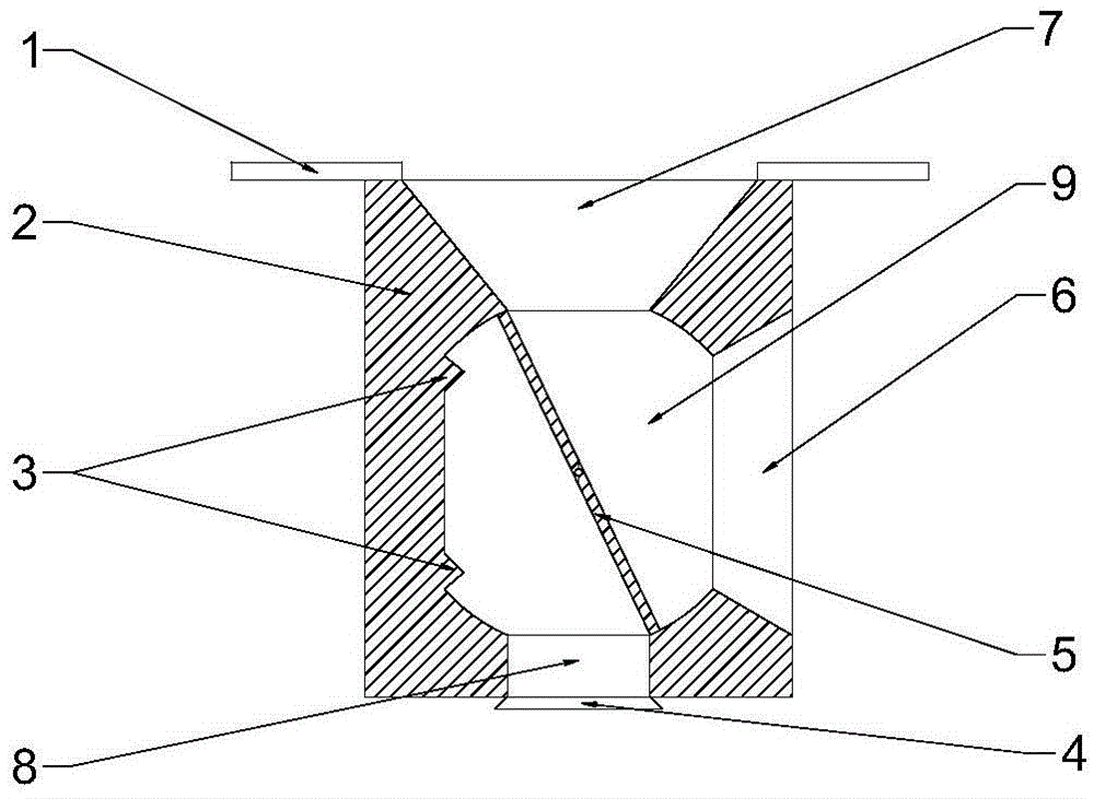
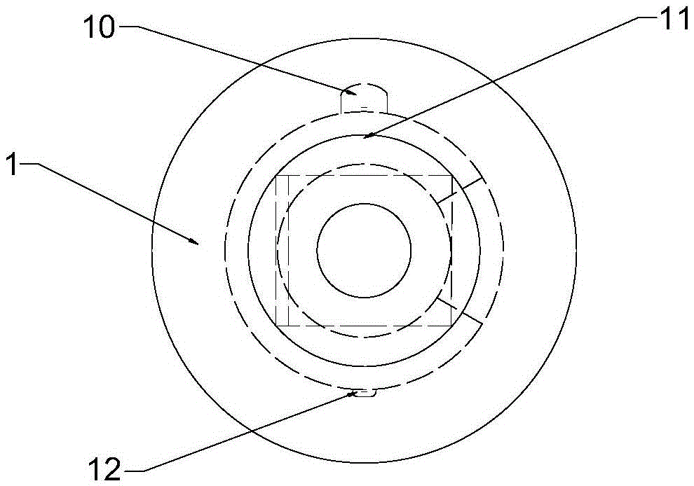
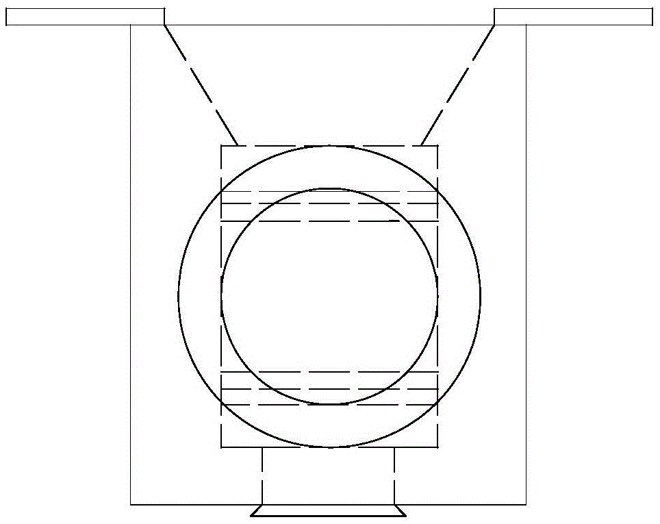
[0046] Such as Figure 1-7 As shown, the invention provides a thermostat, comprising:

[0047] The valve body assembly includes the valve body 2, the fixed positioning buckle 1 arranged above the valve body 2, the water inlet 6 connected with the water outlet pipe 13 arranged on the valve body 2, and the water inlet 6 arranged on the valve body 2. The first outlet 8 connected to the water pump water supply pipe 14 on the body, the second output port 7 connected to the radiator water supply pipe 15, the sealing ring 4, and the rear cover 12 of the rotating shaft.

[0048] The variable channel assembly includes a variable channel baffle plate 5 arranged in the inner cavity, a limit pin 3 arranged inside the valve body 2, an internal cavity 9, a rotating shaft 11, and a motor 10 for driving the baffle.

[0049] The control unit consists of a temperature sensor and a controller.

[0050] The motor works according to the controller signal, and drives the variable flow channel baf...


PUM


Abstract

The invention relates to a thermostat of an engine cooling system, in particular to a thermostat driven by an electric motor. A variable channel thermostat, comprising a valve body with an internal cavity, a water inlet connected to a water jacket outlet pipe on the right side of the valve body, and a first outlet connected to a water pump water supply pipe under the valve body, The second water outlet above the valve body is connected to the water supply pipe of the radiator; the internal cavity is provided with a variable flow channel baffle, and the variable flow channel baffle is connected to the motor through the central shaft; half of the variable flow channel baffle is on the The first outlet rotates between the two sides, and the corresponding other half rotates between the two sides of the second water outlet, and the rotation angle of the variable channel baffle is controlled by the motor. The invention is driven by a motor, and responds quickly when the working condition of the engine changes. Different operating strategies can be adopted to improve engine performance according to changes in engine operating conditions. Finally, due to the controllable flow area, precise control of the circulation volume of different circulating cooling water can be realized, which is beneficial to the optimization of the cooling system.

Description

technical field [0001] The invention relates to a thermostat of an engine cooling system, in particular to a thermostat driven by an electric motor. Background technique [0002] The flow path of the existing thermostat is rough and varied. When the fluid passes through the thermostat, it experiences several times of zooming, throttling, impact, etc., resulting in a huge pressure drop of the fluid in this section, resulting in a huge power consumption of the water pump, which is not Conducive to saving energy. [0003] In addition, the existing thermostats generally only have one set of operating characteristic curves (temperature-lift relationship curve). The working temperature is low, the initial opening temperature is generally around 80°C, and the full opening temperature is generally around 95°C, and the opening / closing of the thermostat is only controlled by the internal temperature-sensing wax. When the coolant temperature reaches or exceeds the thermostat After th...

Claims


Application Information

Patent Timeline
Patent Type & Authority Applications(China)
IPC IPC(8): F01P7/16
CPCF01P7/167
Inventor 熊树生郑宜坤黄晓波毛彬滔章昱帆孙亚博应智超宋洪健周超
Owner ZHEJIANG UNIV
Why Eureka
Try Eureka