Two-phase outwards-convex wheel shock-wave roller pin and roller block transmission internal combustion engine

An external cam, internal combustion engine technology, applied in the direction of machine/engine, mechanical equipment, combustion process measures, etc., can solve the problems of difficult processing, manufacturing, assembly, complex structure, large vibration, etc., to avoid vibration excitation, high transmission efficiency, The effect of small shock and vibration

Inactive Publication Date: 2016-06-15
SICHUAN UNIV
View PDF3 Cites 0 Cited by
  • Summary
  • Abstract
  • Description
  • Claims
  • Application Information

AI Technical Summary

Problems solved by technology

Since this kind of internal combustion engine relies on the linear motion of the piston and the planar motion of the connecting rod to press and drive the crankshaft to rotate, there is a large friction between the kinematic pairs, resulting in low transmission efficiency of the internal combustion engine.
These existing crankshaft connecting rod type internal-combustion engines also have the following main disadvantages: large volume; the unbalanced c

Method used


Image

  • Two-phase outwards-convex wheel shock-wave roller pin and roller block transmission internal combustion engine
  • Two-phase outwards-convex wheel shock-wave roller pin and roller block transmission internal combustion engine
  • Two-phase outwards-convex wheel shock-wave roller pin and roller block transmission internal combustion engine

Examples


Embodiment Construction

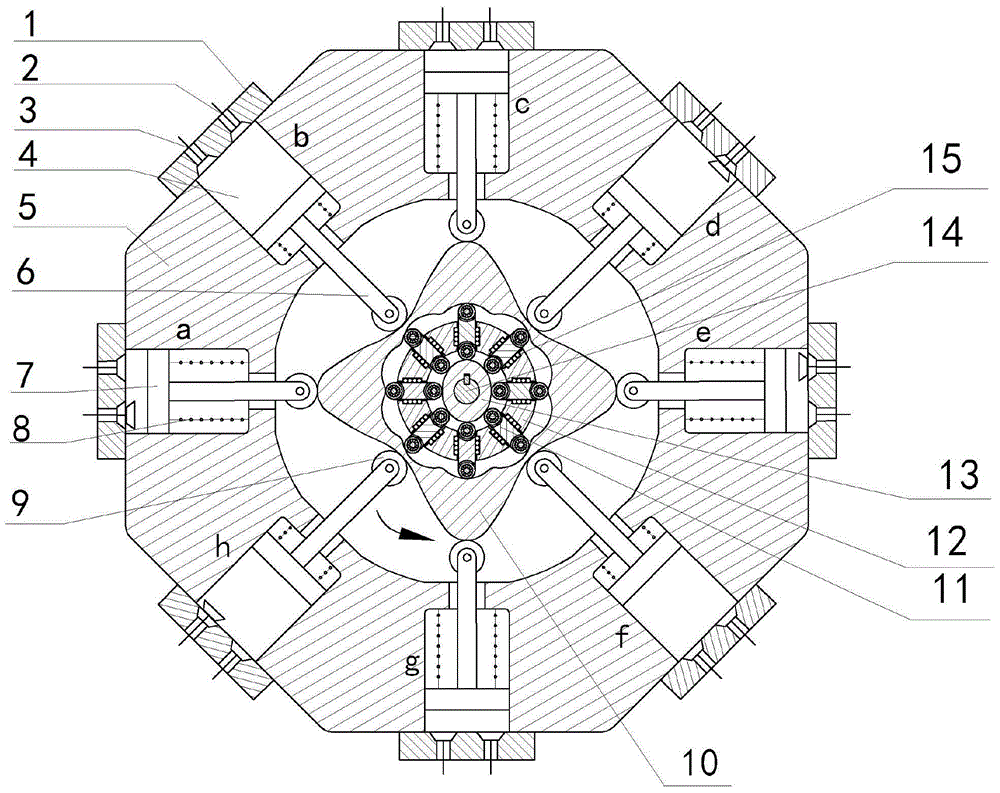
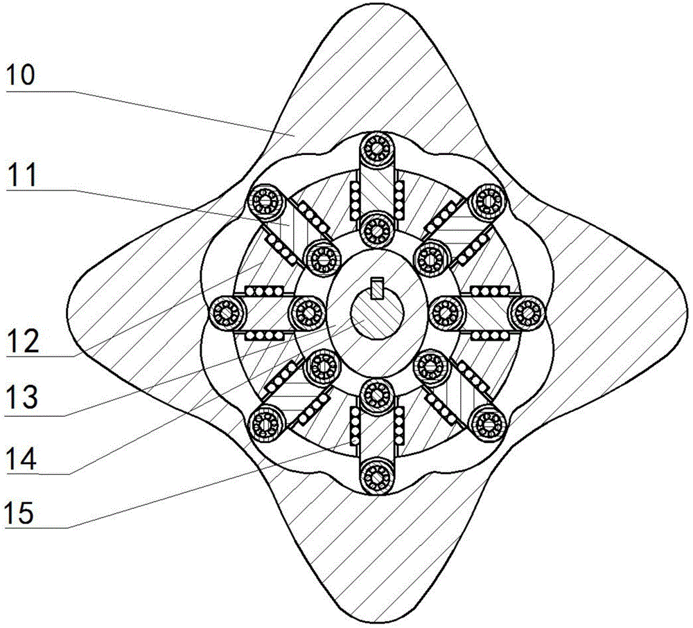
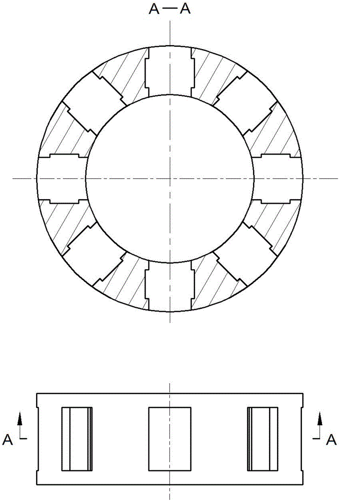
[0040] Figure 1 to Figure 5 The shown two-phase external cam shock wave needle roller block transmission internal combustion engine consists of cylinder head (1), exhaust valve (2), intake valve (3), cylinder (4), cylinder block (5), push rod (6), piston (7), spring (8), roller (9), convex internal gear (10), movable tooth of needle roller block (11), movable gear rack (12), two-phase external cam (13), output shaft (14), needle roller (15) etc. are formed. Eight cylinders (4) are symmetrically and evenly arranged around the outer convex internal gear (10), and the outer convex inner two-phase shock wave needle roller block transmission mechanism converts the reciprocating linear motion of the piston (7) into the output shaft (14) The rotary motion of the cylinder - the cylinder piston (7) directly acts on the convex internal gear (10) through the push rod (6), pushing the external convex internal gear (10) to rotate, and the power is transmitted by the external convex inter...


PUM


Abstract

The invention relates to the field of gas power, in particular to a two-phase outwards-convex wheel shock-wave roller pin and roller block transmission internal combustion engine. According to the novel internal combustion engine provided by the invention, eight cylinders are annularly, symmetrically and evenly distributed on the periphery of an outwards-convex inner gear, and resultant force on the outwards-convex inner gear is zero; cylinder pistons directly act on the outwards-convex inner gear through push rods, and power is transmitted to an output shaft in key joint with a two-phase outwards-convex wheel from the outwards-convex inner gear through transmission of two-phase outwards-convex wheel shock-wave roller pin and roller block movable teeth. According to the internal combustion engine, connecting rods and crankshafts of traditional internal combustion engines are omitted, a two-phase outwards-convex wheel shock-wave roller pin and roller block transmission mechanism of the engine is free of eccentric mass and has the characteristic of inertia force and working load self-balancing, and the rotating speed of the output shaft is determined by the transmission ratio of the movable teeth; if a movable tooth rack is fixed, the two-phase outwards-convex wheel conducts output at a high speed, and the internal combustion engine can be widely applied to the fields needing high rotating speeds, such as helicopter engines and small generators; when the output rotating speed is fixed, emission of harmful gas can be reduced. The internal combustion engine is simple and compact in structure, small in axial size, self-balanced in stress and stable in operation.

Description

technical field [0001] The invention relates to the field of gas power, more specifically, a two-phase external cam shock wave needle roller block transmission internal combustion engine. Background technique [0002] At present, commonly used internal combustion engines (engines) are composed of a body, a crank linkage mechanism, a valve mechanism, a cooling system, a lubrication system, a fuel system, and an ignition system. stroke. The transmission mechanism of this type of internal combustion engine uses a crank-connecting rod mechanism, which transmits the power of the piston to the crankshaft through the connecting rod, and converts the reciprocating linear motion of the piston into the rotary motion of the crankshaft. Because this internal combustion engine presses and drives the crankshaft to rotate by the linear motion of the piston and the planar motion of the connecting rod, there is greater friction between the kinematic pairs, resulting in low transmission effi...

Claims


Application Information

Patent Timeline
IPC IPC(8): F02B75/02F02B75/22F02B75/32
CPCF02B75/32F02B75/02F02B75/222F02B2075/027F02B2075/1832F02B2700/02
Inventor 梁尚明邓成军陈飞宇徐毅李华林光春
Owner SICHUAN UNIV
Why Eureka
Try Eureka