A beer keg filling cleaning valve

A technology of beer kegs and cleaning valves, which is applied in the direction of keg/cask filling, packaging, valve lift, etc., which can solve the problems of inability to realize continuous filling of beer kegs, inability to clean beer kegs, low filling efficiency, etc., and achieve functional Complete, improve the taste, reduce the effect of air bubbles

Active Publication Date: 2019-02-22
NANJING LEHUI LIGHT IND EQUIP
View PDF5 Cites 0 Cited by
  • Summary
  • Abstract
  • Description
  • Claims
  • Application Information

AI Technical Summary

Problems solved by technology

When filling, the valve body does not move, the beer keg is placed above the valve body, and then the valve stem rises so that the top of the valve stem pushes the top of the valve stem to open the wine spear of the beer keg for filling. This filling method has the following disadvantages: 1. The filling valve can only realize filling, and cannot clean the beer kegs before filling; 2. This kind of filling valve cannot realize the continuous filling of beer kegs, and can only connect the beer kegs to the filling valves one by one. After filling, the beer keg is separated from the filling valve, so the filling efficiency is not high
3. The current filling valve cannot determine whether it is well connected with the beer keg and whether the wine spear has been opened, so it may happen that the filling valve is not properly connected and the beer is filled, resulting in waste of beer

Method used


Image

  • A beer keg filling cleaning valve
  • A beer keg filling cleaning valve
  • A beer keg filling cleaning valve

Examples


Embodiment Construction

[0026] The present invention will be described in further detail below through specific examples.

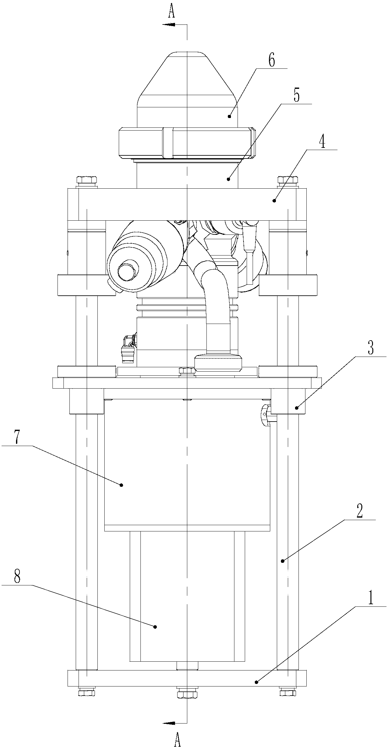
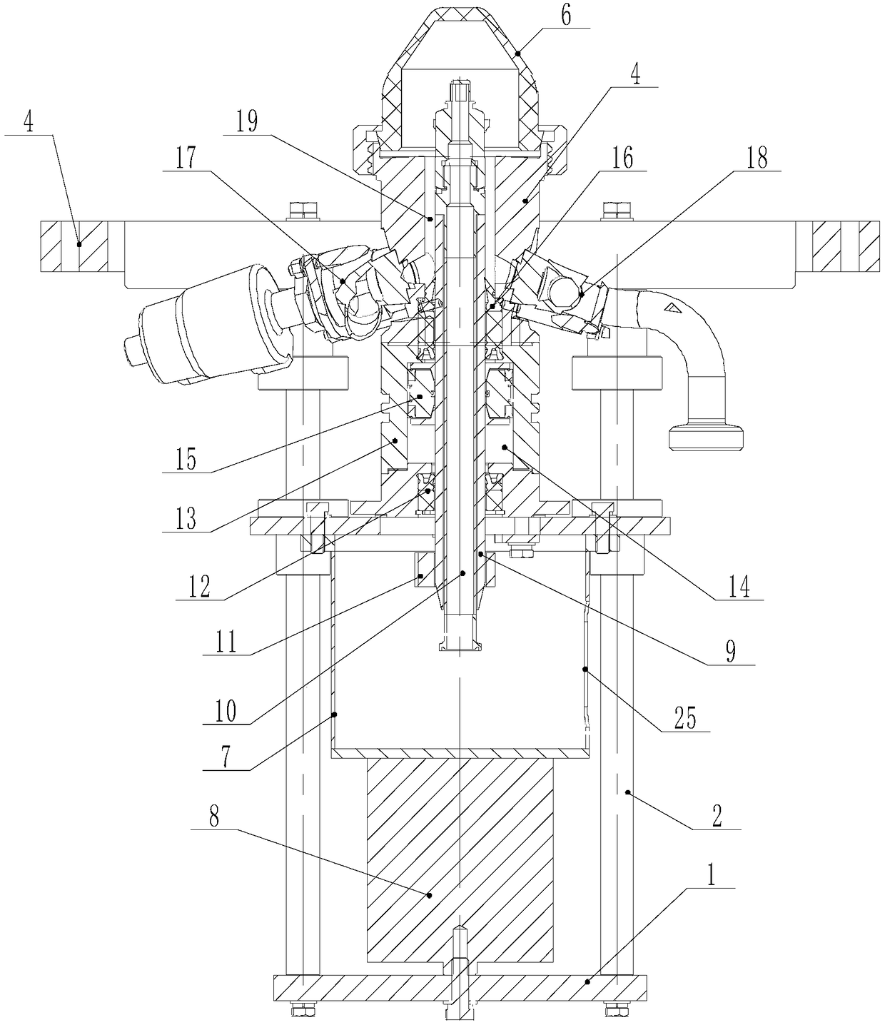
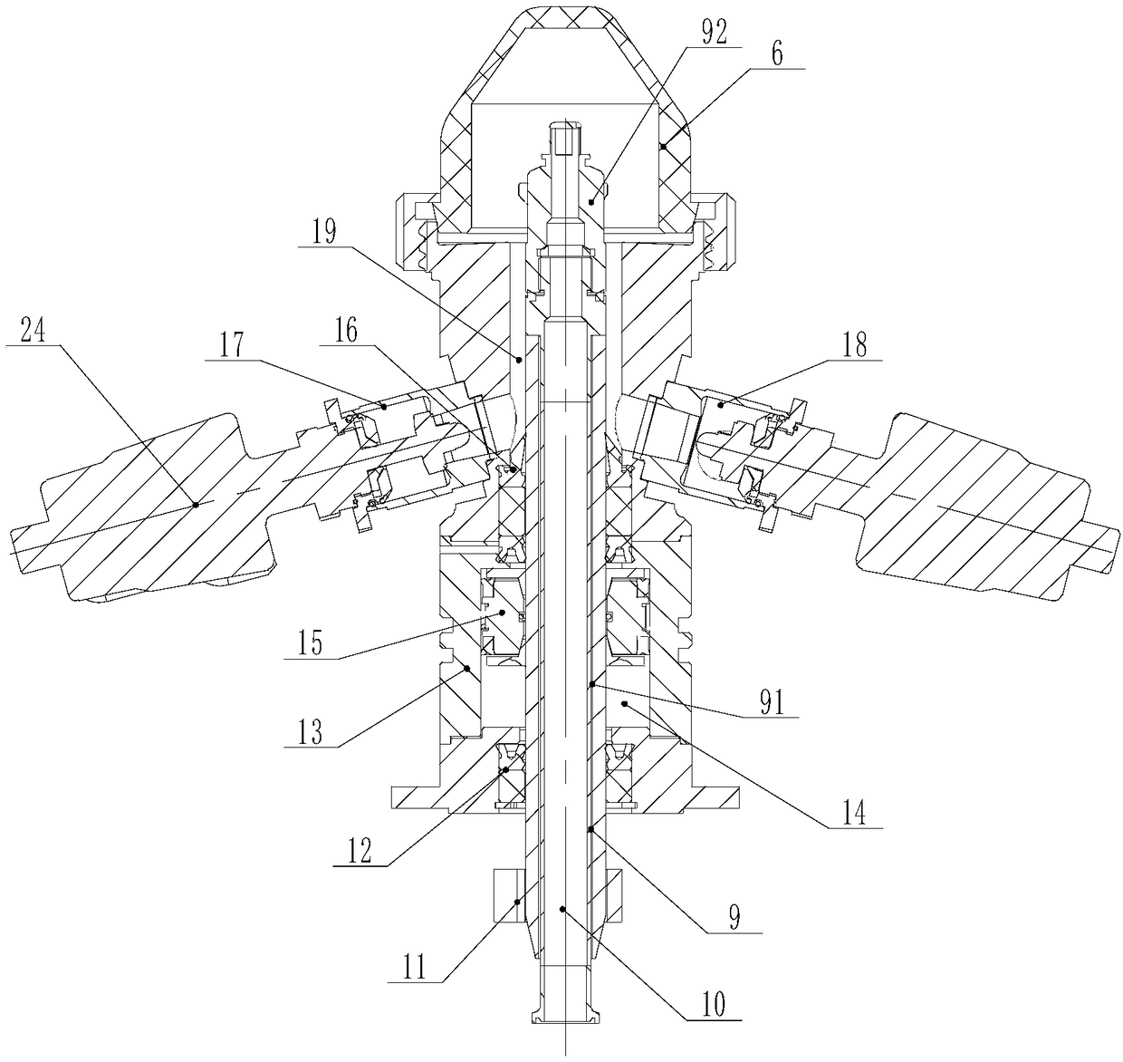
[0027] Such as Figure 1 to Figure 5 As shown, a beer keg filling and cleaning valve includes a valve body 5 and a valve stem 9. The valve stem 9 is axially slidably installed in the valve body 5, and the orientation is determined by the actual working state of the filling and cleaning valve. The valve stem 9 is axially and vertically slidably mounted on the valve body 5, and the valve body 5 is provided with a beer flow passage 19 outside the valve stem 9, and the beer flow passage 19 is used for the flow space of beer during filling , the upper end of the beer flow channel 19 runs through the upper end of the valve body 5, when the top of the valve stem 9 pushes away the wine spear, the beer flow channel 19 communicates with the beer keg inner cavity, the valve body 5 and the valve body The first sealing ring 16 at the lower end of the beer flow channel 19 is installed betwee...


PUM


Abstract

The invention discloses a filling and cleaning valve of a beer barrel. The filling and cleaning valve comprises a valve body and a valve rod, wherein a beer flow channel is arranged on the valve body; a first sealing ring at the lower end of the beer flow channel is mounted between the valve body and the valve rod; a central through hole is formed in the valve rod; a cylinder barrel is fixedly arranged on the bottom of the valve body; a piston in the cylinder barrel is fixedly arranged on the valve rod; a second sealing ring is arranged between the bottom of the cylinder barrel and the valve rod; a descending chamber is formed between the first sealing ring and the piston; an ascending chamber is formed between the piston and the second sealing ring; an ascending gas inlet and a descending gas inlet which communicate with the ascending chamber and the descending chamber are respectively formed in the cylinder barrel; and the valve rod is vertically mounted on a bracket in a sliding manner, and is driven by a valve body lifting power device. The filling and cleaning valve of the beer barrel not only can realize online equal-pressure filling of the beer barrel, but also can clean the beer barrel before filling, so that the filling efficiency is improved, and the hygienic quality is improved.

Description

technical field [0001] The invention relates to a filling cleaning valve, in particular to a beer keg filling cleaning valve. Background technique [0002] At present, draft beer is more and more subject to people's favor, and the beer barrel that is used to dress draft beer can be filled with beer repeatedly by filling machine, can be recycled, and the service life is long. However, the current filling of beer kegs is to use a special filling valve for filling. The filling valve includes a valve body and a valve stem. The valve stem is axially slidably installed in the valve body. The beer flow channel outside the rod, the upper end of the beer flow channel passes through the upper end of the valve body, the first sealing ring at the lower end of the beer flow channel is installed between the valve body and the valve stem, and the valve body is provided with A wine inlet and an emptying port communicated with the beer flow channel, the wine inlet and the emptying port are ...

Claims


Application Information

Patent Timeline
Patent Type & Authority Patents(China)
IPC IPC(8): F16K11/22F16K1/32F16K31/122F16K37/00B67C7/00B67C3/30
CPCB67C3/30B67C7/00F16K1/32F16K11/22F16K31/122F16K37/0083F16K37/0091
Inventor 陈小平黄粤宁陈山林
Owner NANJING LEHUI LIGHT IND EQUIP
Why Eureka
Try Eureka