Method for calibrating any peak delay amount of photoelastic modulator

A photoelastic modulator and calibration method technology, applied in optics, instruments, nonlinear optics, etc., can solve the problems that single photon counting technology cannot be used for photoelastic modulator calibration, light intensity fluctuation, and inability to calibrate photoelastic modulators, etc.

Inactive Publication Date: 2016-06-15
FUDAN UNIV
View PDF1 Cites 12 Cited by
  • Summary
  • Abstract
  • Description
  • Claims
  • Application Information

AI Technical Summary

Problems solved by technology

For the calibration of a single peak delay, if the peak delay that the photoelastic modulator can achieve in some bands is less than the peak delay during calibration, the photoelastic modulator cannot be calibrated in this band
In addition, the fluctuation of light intensity will seriously affect the calibration accuracy
Complex single-photon counting techniques are not practical for photoelastic modulator calibration

Method used


Image

  • Method for calibrating any peak delay amount of photoelastic modulator
  • Method for calibrating any peak delay amount of photoelastic modulator
  • Method for calibrating any peak delay amount of photoelastic modulator

Examples


Embodiment 1

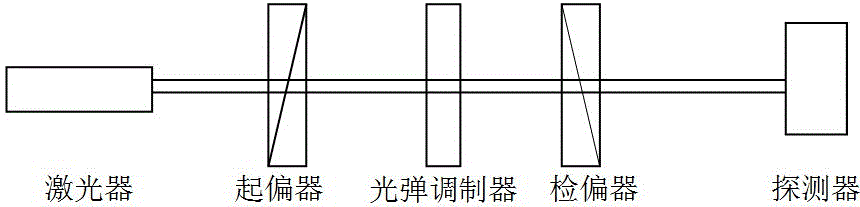
[0026] The optical path diagram for calibrating the photoelastic modulator is shown in figure 1 shown.

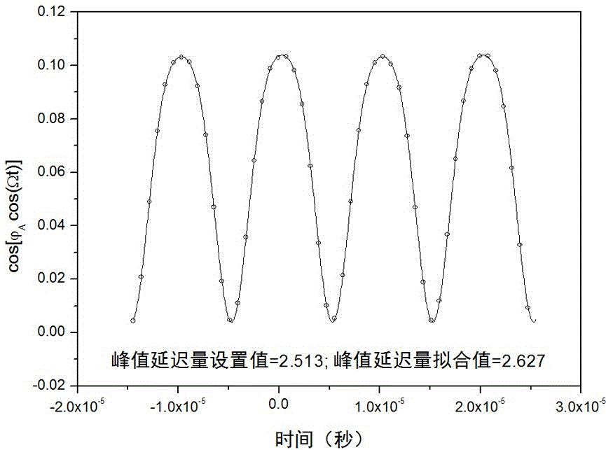
[0027] The He-Ne laser passes through a polarizing prism (polarizer) with an azimuth angle of 45°, passes through a photoelastic modulator with an azimuth angle of 0°, and then passes through a polarizing prism (analyzer) with an azimuth angle of -45°, and then Light is incident on the photodiode, and the electrical signal output by the photodiode is detected by an oscilloscope. Set the amount of peak delay on the photoelastic modulator controller, and the waveform on the oscilloscope changes accordingly. Digital output of the waveform on the oscilloscope. use The function fit obtains the fitted value of the peak delay amount. Within the adjustable range of the peak delay, gradually change the set value of the peak delay and sequentially fit to obtain the corresponding peak delay fitting value. Fitting obtains the linear relationship between the fitted value of the pe...


PUM


Abstract

The invention belongs to the technical field of signal modulation, and specifically relates to a method for calibrating the peak delay amount of a photoelastic modulator. The technical scheme that the method adopts is as follows: the photoelastic modulator is placed between two polarizers; incident light passes through a polarizer, the photoelastic modulator and an analyzer in sequence, and is then measured by a detector; the peak delay amount of the photoelastic modulator is set, and the detector obtains a waveform; and the waveform is output as a digital signal, and software is adopted to perform fitting on the waveform, thereby obtaining an actual value (i.e., a fitted value) of the peak delay amount. A set value required to obtain any peak delay amount is calculated based on a relation between a set value and an actual value of the peak delay amount. The method provided by the invention can calibrate any peak delay amount of the photoelastic modulator, and is mainly used for signal modulation technology and error correction.

Description

technical field [0001] The invention belongs to the technical field of signal modulation, and in particular relates to a method for calibrating any peak delay of a photoelastic modulator. Background technique [0002] The photoelastic modulator is a phase modulation device based on the photoelastic effect. It has the advantages of large clear aperture, large full field of view, high modulation frequency, wide band, low driving voltage, and low power consumption. It is a polarization modulation technology. The core device in the device has a wide range of applications in the fields of biophysics, physical chemistry, and crystal growth. [0003] Precise calibration of the photoelastic modulator is the premise and basis for accurate measurement. Calibration of photoelastic modulators usually adopts methods such as oscilloscope characteristic waveform, fundamental frequency component, second harmonic component or DC component being zero or extreme value, single photon counting ...

Claims


Application Information

Patent Timeline
Patent Type & Authority Applications(China)
IPC IPC(8): G01D18/00G02F1/01
CPCG01D18/00G02F1/0131
Inventor 朱成钢陈儒费义艳
Owner FUDAN UNIV
Why Eureka
Try Eureka