
Mechanical induction plate

An induction plate and mechanical technology, applied in the field of sensors, can solve problems such as low transient accuracy, poor stress, and inaccurate measurement results, and achieve the effect of improving accuracy and sensitivity and ensuring consistency

Active Publication Date: 2016-06-15
SHANTOU GOWORLD DISPLAY TECH CO LTD
View PDF6 Cites 5 Cited by
  • Summary
  • Abstract
  • Description
  • Claims
  • Application Information

AI Technical Summary

Problems solved by technology

[0003] Figure 1A , Figure 1B It is a structural schematic diagram of a mechanical induction plate at present, such as Figure 1A As shown, the first conductive film 01 and the second conductive film 02 are separated by the substrate 03, as Figure 1B As shown, when the mechanical induction plate is bent, its stress neutral surface 06 is as Figure 1B As shown, the first conductive film 01 and the second conductive film 02 are divided into compressive stress and tensile stress, and the direction of normal stress change of the first conductive film 01 and the second conductive film 02 is opposite, so there is an obvious stress difference. However, due to the large distance between the first conductive film 01 and the second conductive film 02, when the temperature changes (such as the temperature change caused by body temperature when the finger is pressed), the first strain resistance 04 and the second strain resistance There is a large heat transfer time between resistors 05, and there is a large difference in temperature, which makes the transient accuracy of the measurement results not high
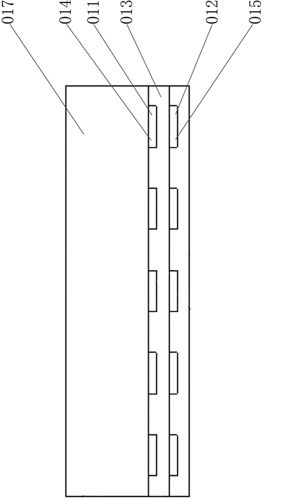
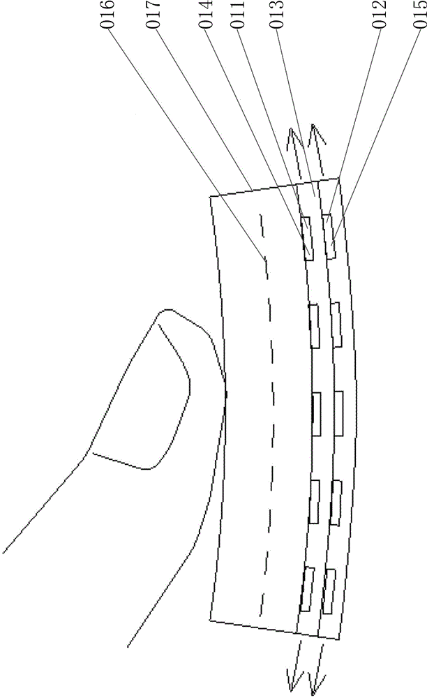
[0004] Figure 2A , Figure 2B It is a structural schematic diagram of another mechanical induction plate at present, such as Figure 2A As shown, the first conductive film 011 and the second conductive film 012 are separated by a very thin insulating layer 013, so the temperature difference between the first strain resistance 014 and the second strain resistance 015 is very small, as shown in Figure 2B As shown, when the mechanical sensing plate is bent, its stress neutral surface 016 is in the middle of the substrate 017. Since the plane distance between the first conductive film 011 and the second conductive film 012 is very small, the first conductive film 011, the second conductive film 012 Not only the tensile stress generated by the second conductive film 012, but also the stress change values ​​of the first conductive film 011 and the second conductive film 012 are very close, which also makes the measurement results inaccurate
[0005] Therefore, for this kind of mechanical sensor, in order to reduce the temperature difference between the first conductive film and the second conductive film, it is necessary to reduce the interplanar distance between the first conductive film and the second conductive film, and in order to improve the temperature difference between the first conductive film and the second conductive film. If the stress difference between the first conductive film and the second conductive film needs to be increased, the existence of this contradiction makes it difficult to obtain accurate measurement results

Method used


Image

  • Mechanical induction plate
  • Mechanical induction plate
  • Mechanical induction plate

Examples


Embodiment Construction

[0032] Further description will be given below in conjunction with the accompanying drawings and preferred embodiments of the present invention.

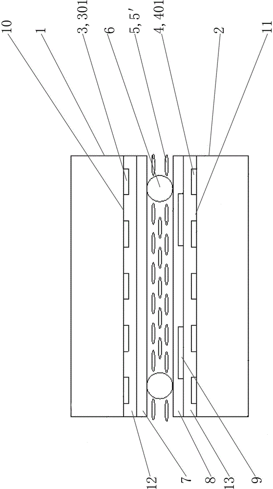
[0033] Such as image 3 , Figure 4 , Figure 5 As shown, this mechanical induction plate includes a first plate body 1, a second plate body 2 arranged in parallel, a first conductive film 3, a second conductive film 4, a shearing layer 5, a spherical support 6, a first Alignment layer 7, second alignment layer 8, sensing circuit ( image 3 , Figure 4 , Figure 5 not shown in ) and the electrode mechanism 9; the thickness of the first plate body 1 and the second plate body 2 are the same; the inner surface of the first plate body 1 is the first sliding surface 10, and the outer surface of the second plate body 2 is the first sliding surface Two sliding surfaces 11, the first conductive film 3 and the second conductive film 4 are respectively arranged on the first sliding surface 10 and the second sliding surface 11, such as ...


PUM

PropertyMeasurementUnit
thicknessaaaaaaaaaa
thicknessaaaaaaaaaa

Abstract

The invention relates to a mechanical induction plate. The mechanical induction plate is characterized in that: a first conducting film and a second conducting film are respectively arranged on a first sliding surface of a first plate and a second sliding surface of a second plate; the first conducting film and the second conducting film are respectively patterned to form a plurality of corresponding first strain resistors and second strain resistors; a relief course with mobility is arranged between the first sliding surface and the second sliding surface; when the first sliding surface and the second sliding surface are pressed by the external force, the first sliding surface and the second sliding surface slide relatively, and the first plate and second plate are curved, and the first conducting film is stretched so that the positive stress value becomes smaller, and the second conducting film is compressed so that the positive stress value becomes greater; the first strain resistors and the second strain resistors generate very clear differential signals so that the accuracy and the sensitivity for the press force detection are improved; and as the relief course is provided with mobility so that the relief course can be set very thin and the consistency of the temperature is guaranteed and the differential signals can more accurately reflect the press force of the finger on the mechanical induction plate.

Description

technical field [0001] The invention relates to a sensor, in particular to a mechanical induction plate. Background technique [0002] The mechanical sensing plate in the prior art generally includes a first conductive film and a second conductive film overlapping each other. Two strain resistances, the resistance values ​​of the first strain resistance and the second strain resistance respectively form a monotone function with the normal stress values ​​of the first conductive film and the second conductive film, thus, when the pressure applied on the mechanical induction plate appears, For example, when the surface of the pressure sensing plate is pressed with a finger, the bending of the force sensing plate will cause the normal stress on the first conductive film and the second conductive film to change, which can be determined according to the resistance value of the first strain resistance and the second strain resistance change, to detect the pressure, wherein, becau...

Claims


Application Information

Patent Timeline
Patent Type & Authority Applications(China)
IPC IPC(8): G01L1/22
CPCG01L1/22G01L1/2287
Inventor 沈奕苏赞加詹前贤杨秋强黄贵松吕岳敏林铿余荣高嘉桐黄晓银郑少丹郭茂彬
Owner SHANTOU GOWORLD DISPLAY TECH CO LTD
Learn More