Natural circulation phase change heating storage tank

A technology of natural circulation and oil storage tanks, which is applied to tank cars, transport passenger cars, railway car body parts, etc., can solve the problems of large medium loss, high energy consumption, and easy fouling, so as to improve heat exchange efficiency and prolong heat exchange Time, the effect of expanding the contact surface

Inactive Publication Date: 2011-12-07
刘凯
View PDF4 Cites 1 Cited by
  • Summary
  • Abstract
  • Description
  • Claims
  • Application Information

AI Technical Summary

Problems solved by technology

[0002] At present, the single-well oil tanks used in my country's oilfield development mainly include atmospheric pressure elevated tanks and pressure-bearing multifunctional tanks. It does not comply with the safety regulations of GB50183-2004 "Code for Fire Protection of Petroleum and Natural Gas Engineering Design", and in practical applications, there are indeed explosion accidents of large tanks from time to time, which poses great hidden dangers; and the pressure-bearing multifunctional tank cannot burn coal, if the gas source is not enough It will affect the production, and there is also a split structure, that is, the heating furnace is separated from the oil storage tank, and the heat generated by the heating furnace is absorbed by the heat medium, and is forced to be transported to the heat exchanger in the oil storage tank by the circulating pump for heat exchange. However, the heating furnace used is generally an atmospheric furnace, with large loss of medium, frequent addition, small temperature difference (water temperature is less than 100 degrees Celsius), easy scaling, low thermal efficiency, and it is difficult to meet the actual production needs; and the long-term continuous use of the circulating pump, the failure rate high energy consumption

Method used


Image

  • Natural circulation phase change heating storage tank
  • Natural circulation phase change heating storage tank
  • Natural circulation phase change heating storage tank

Examples


Embodiment 1

[0015] Embodiment 1: in combination with Figure 1-2 , to further describe the present invention:

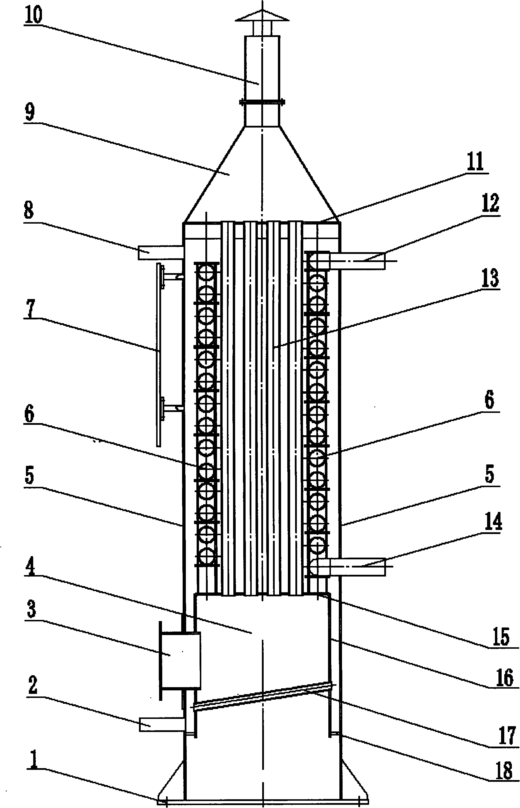
[0016] The present invention is mainly composed of a phase change heating furnace H, an oil storage tank and a pipeline system. The phase change heating furnace is connected to the oil storage tank through the pipeline system; the oil storage tank has a normal pressure tank or a pressure separation tank Two forms; the pipeline system is composed of crude oil pipelines, gas pipelines, water vapor circulation pipelines, and valves. The crude oil pipelines and gas pipelines are laid under the foundation line; The water vapor enters the tank pipeline, and the lower part is the condensate return pipeline.

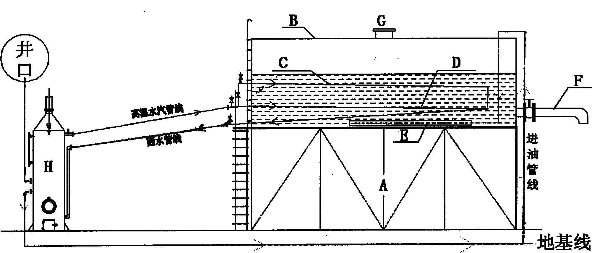
[0017] Among them, the atmospheric tank is a horizontal cuboid, consisting of a tank base A, a tank body B, an upper heat exchanger C, a lower heat exchanger D, a crude oil diffuser E, an oil discharge port F, and a breathing port G, and the tank body B is fixed. On the tank bas...

Embodiment 2

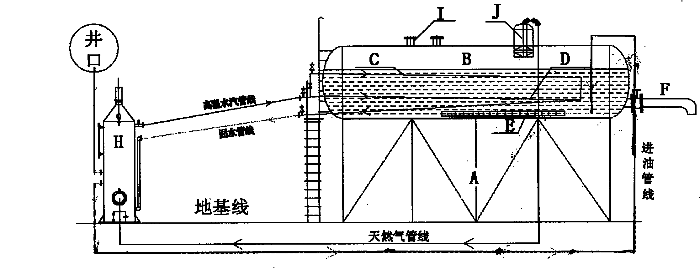
[0022] Embodiment 2: in combination with image 3 , to further describe the present invention:

[0023] Another pressure-bearing separation tank is a horizontal cylinder, which consists of a tank base A, a tank body B, an upper heat exchanger C, a lower heat exchanger D, a crude oil diffuser E, an oil discharge port F, a safety valve I and a gas distributor. The tank body B is fixed on the tank seat A, the upper heat exchanger C, the lower heat exchanger D, and the crude oil diffuser E are respectively fixed at the bottom of the tank body, and the safety valve I and the gas distribution bag J are placed in the tank top of the body.

[0024] The advantages of the present invention are as follows:

[0025] 1. Safe and reliable, the distance between the heating furnace and the oil storage tank is more than 15 meters, in line with the safety fire regulations of GB50183-2004 "Code for Fire Protection of Oil and Gas Engineering Design"; equipped with a thermostatic control valve, ...


PUM


Abstract

The invention relates to a natural circulation phase-change heating oil storage tank. The technical scheme is as follows: the natural circulation phase-change heating oil storage tank consists of a phase-change heating furnace, an oil storage tank and a pipeline system, wherein the phase-change heating furnace is connected with the oil storage tank by the pipeline system; the oil storage tank comprises two forms such as a normal pressure tank or a bearing and separating tank; the pipeline system consists of a crude oil pipeline, a gas pipeline and water-vapor circulation pipelines, and the crude oil pipeline and the gas pipeline are laid under a foundation line; the water-vapor circulation pipelines are erected from the air, and are divided into an upper layer and a lower layer, wherein the upper layer is high-temperature water-vapor tank inlet pipelines and the lower layer is a condensed water return pipeline. When in working, phase change is utilized for heat transferring so as to realize backflow naturally without needing a forced circulation system such as a hot water pump and the like, and the heat efficiency reaches or exceeds that of the 'heart-burn' structure; the matched heating furnace combines the advantages of a water jacket furnace and a pipe type furnace, and is equipped with a single-well coiled pipe; especially, a hearth adopts a water-cooling wall structure, and a fire grate adopts water-cooling pipes without using refractory bricks, so that the volume is smaller, the weight is light, the heat loss is less, and the heat efficiency is high. The heating furnace can achieve the purpose of burning three types of fuels such as coal, gas and oil simultaneously.

Description

1. Technical field: [0001] The invention relates to an oilfield heating device, in particular to a natural circulation phase change heating oil storage tank suitable for crude oil heating, storage and shipment of oilfield single-well pulling tanks and multi-functional tanks. 2. Background technology: [0002] At present, the single-well oil tanks used in my country's oilfield development mainly include atmospheric pressure elevated tanks and pressure-bearing multifunctional tanks. It does not comply with the safety regulations of GB50183-2004 "Code for Fire Protection of Oil and Gas Engineering Design", and in practical applications, large tank explosion accidents do occur from time to time, which poses great hidden dangers; and pressure-bearing multi-functional tanks cannot burn coal, if the gas source is not enough It will affect the production, and there is also a split structure, that is, the heating furnace is separated from the oil storage tank, and the heat generated by...

Claims


Application Information

Patent Timeline
Patent Type & Authority Applications(China)
IPC IPC(8): B65D88/74
Inventor 潘敏勇丁明庆许海峰张其民刘凯
Owner 刘凯
Why Eureka
Try Eureka