Heat exchange pipe for petrochemical machinery

A heat exchange tube and machinery technology, applied in the field of heat exchange tubes for petrochemical machinery, can solve the problems of insufficient heat exchange, unfavorable normal use of mechanical equipment, low work efficiency, etc., to avoid leakage, improve sealing, and strengthen exchange. The effect of thermal efficiency

Active Publication Date: 2017-03-15
江苏泽楚建设有限公司
View PDF7 Cites 1 Cited by
  • Summary
  • Abstract
  • Description
  • Claims
  • Application Information

AI Technical Summary

Problems solved by technology

[0004] In view of the deficiencies in the prior art, the purpose of the present invention is to provide a heat exchange tube for petrochemical machinery to solve the problem of low heat exchange efficiency and insufficient heat exchange of the heat exchange tubes for petrochemical machinery in the prior art mentioned in the background art. It is not conducive to the normal use of mechanical equipment. During heat exchange, the contact surface of the heat exchange fluid between the pipe body and the outside world is small, and multiple cycles are required to reduce the temperature inside the pipe. The heat exchange is slow and the work efficiency is low. The present invention is easy to use and easy to operate , good stability and high reliability

Method used


Image

  • Heat exchange pipe for petrochemical machinery
  • Heat exchange pipe for petrochemical machinery
  • Heat exchange pipe for petrochemical machinery

Examples


Embodiment Construction

[0017] In order to make the technical means, creative features, goals and effects achieved by the present invention easy to understand, the present invention will be further described below in conjunction with specific embodiments.

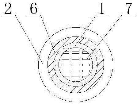
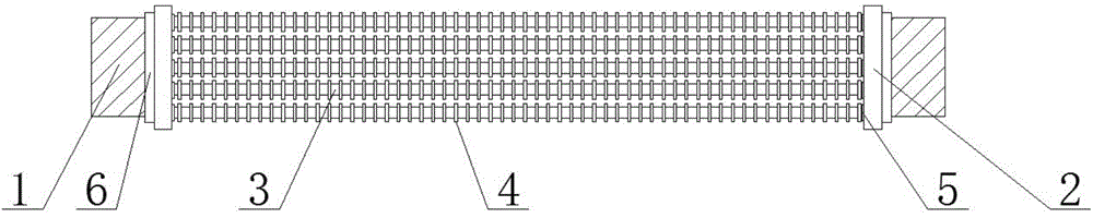
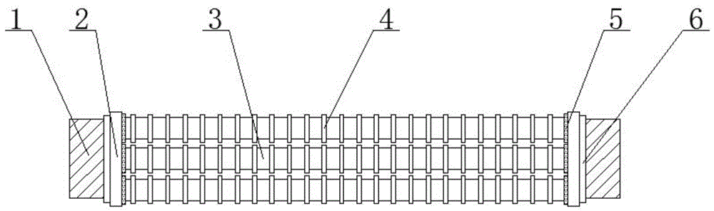
[0018] see Figure 1-3 , the present invention provides a technical solution: a heat exchange tube for petrochemical machinery, including a capillary heat exchange tube body 3, capillary heat exchange tube body 3 is provided with capillary tube heat exchange fins 4, and capillary heat exchange tube body 3 Both ends are provided with input and output buffer tubes 2, and the two ends of the input and output buffer tubes 2 close to the capillary heat exchange tube body 3 are provided with internal heat exchange fluid input and output nozzles 7, and the capillary heat exchange tube body 3 is connected with the input and output tubes. The connection of the buffer tube 2 is provided with a capillary sealing rubber ring 5, and the end of the input and ou...


PUM


Abstract

The invention provides a heat exchange pipe for petrochemical machinery. The heat exchange pipe comprises capillary heat exchange pipe bodies, the capillary heat exchange pipe bodies are provided with capillary pipe heat exchange fins, and the two ends of the capillary heat exchange pipe bodies are both provided with input and output buffer pipes. The portions, close to the two ends of the capillary heat exchange pipe bodies, of the interiors of the input and output buffer pipes are both provided with internal heat exchange fluid input and output pipe openings. The connection positions of the capillary heat exchange pipe bodies and the input and output buffer pipes are provided with capillary pipe sealing rubber ring, the ends, away from the capillary heat exchange pipe bodies, of the input and output buffer pipes are provided with threaded connection pipe heads, and the sides, close to the input and output buffer pipes, of the threaded connection pipe heads are provided with connection pipe head sealing rings. The strip-shaped capillary heat exchange pipe bodies are distributed in an array manner, the contact areas of heat exchange fluid and the pipe bodies are increased, thereby raising the heat exchange speed and improving heat exchange efficiency, and it is convenient to protect normal operation of the petrochemical machinery; meanwhile, the capillary heat exchange pipe bodies are evenly provided with the capillary pipe heat exchange fins, so that heat exchange efficiency is further enhanced.

Description

technical field [0001] The invention relates to a heat exchange tube for petrochemical machinery, which belongs to the field of petrochemical machinery and equipment. Background technique [0002] The heat exchange tube is one of the components of the heat exchanger. It is placed in the cylinder and used for heat exchange between the two media. The center distance of the heat exchange tube must ensure that when the tube is connected to the tube sheet, the tube bridge (two adjacent tubes Clearance distance between) have sufficient strength and width. When the pipes need to be cleaned, there will be a channel for cleaning. The center distance of the heat exchange tube should not be less than 1.25 times the outer diameter of the heat exchange tube. Common materials include carbon steel, low alloy steel, stainless steel, copper, copper-nickel alloy, aluminum alloy, titanium, etc. In addition, there are some non-metallic materials, such as graphite, ceramics, polytetrafluoroeth...

Claims


Application Information

Patent Timeline
Patent Type & Authority Applications(China)
IPC IPC(8): F28D7/16F28F1/30F28F9/26F28F11/02
CPCF28D7/16F28F1/30F28F9/266F28F11/02
Inventor 杨冬吴兴滨
Owner 江苏泽楚建设有限公司
Why Eureka
Try Eureka