
Glass light guide plate and manufacturing method thereof

A technology of glass light guide plate and manufacturing method, which is applied in the direction of light guide, optics, optical components, etc., can solve the problems of unfavorable product quality, easy to fall off, and differences in chemical properties of inks, etc. good strength effect

Inactive Publication Date: 2016-06-15
NANJING CEC PANDA LCD TECH
View PDF5 Cites 8 Cited by
  • Summary
  • Abstract
  • Description
  • Claims
  • Application Information

AI Technical Summary

Problems solved by technology

At present, there are two ways to make dots on the glass light guide plate: one is the method of printing dots, which has the advantage that it can be mass-produced, but the disadvantages are: 1. Due to the difference in chemical properties between ink and glass, it is easy to produce chromatic aberration; 2. Due to The adhesion of the ink is poor, so it is easy to fall off or partially peel off; 3. For ultra-small dots, such as dots below 0.1mm, its mass production is poor
The other is to make dots for laser dots, but it will form fine cracks around the dots. Because the glass itself is brittle, it will affect the strength of the glass, which is not conducive to the quality of the product.

Method used


Image

  • Glass light guide plate and manufacturing method thereof
  • Glass light guide plate and manufacturing method thereof
  • Glass light guide plate and manufacturing method thereof

Examples


Embodiment Construction

[0016] Below in conjunction with accompanying drawing and specific embodiment, further illustrate the present invention, it should be understood that these embodiments are only used to illustrate the present invention and are not intended to limit the scope of the present invention, after having read the present invention, those skilled in the art understand various aspects of the present invention Modifications in equivalent forms all fall within the scope defined by the appended claims of this application.

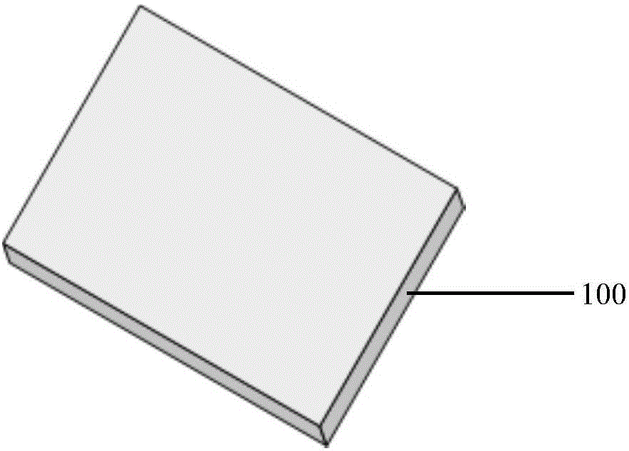
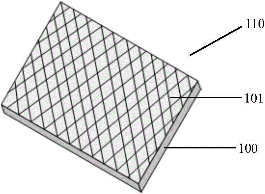
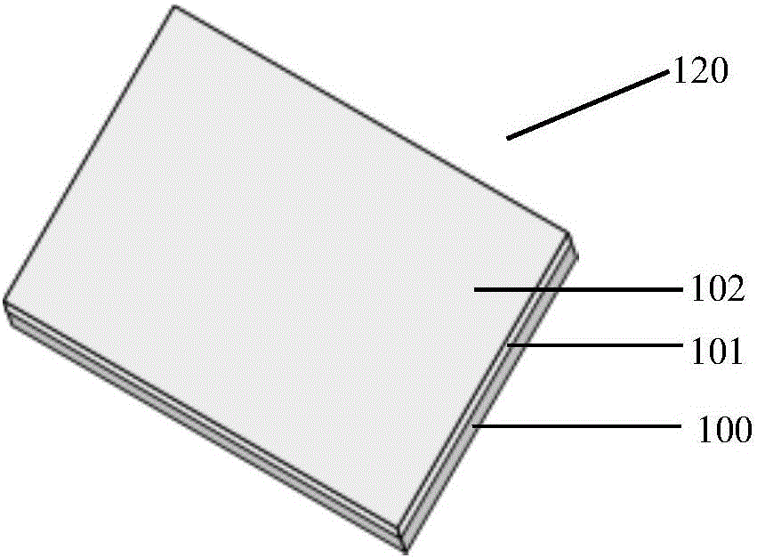
[0017] The invention provides a method for manufacturing a glass light guide plate, comprising the following steps: the first step is coating of photoresist. Such as figure 1 As shown, the glass light guide plate 100 is cleaned, heated and dried to prevent the surface from attaching moisture; then a layer of active group 101, such as hexamethyldisilamine (HMDS), is coated on the surface of the glass light guide plate 100 to increase Adhesion between photoresist and glas...


PUM


Abstract

The invention discloses a glass light guide plate manufacturing method. The method comprises the following steps: the glass light guide plate is coated with a photoresist; a mask plate with a glass light guide plate screen dot pattern is manufactured; the photoresist is exposed through the mask plate; the photoresist is developed; hydrofluoric acid is sprayed on the surface of the photoresist to form the screen dots of the glass light guide plate; and the remaining photoresist is stripped and the glass light guide plate is cleaned. The glass light guide plate manufactured in the manufacturing method of the invention has the advantages of no color difference, no falling, good screen dot effects, no cracks, good glass strength, no brittle fracture, good light guide performance, and industrial batch production.

Description

technical field [0001] The invention belongs to the field of liquid crystal display devices, and in particular relates to a glass light guide plate and a manufacturing method thereof. Background technique [0002] In the liquid crystal display, the light guide plate is mainly used to convert the line light source emitted by the light source into a surface light source, so as to make the brightness of the display screen uniform. Traditional light guide plates are made of polymethyl methacrylate (PMMA), polycarbonate (PC), etc. Recently, a light guide plate made of glass substrate has been introduced, which is stronger than traditional light guide plates. The module can be made thinner on TV products. At present, there are two ways to make dots on the glass light guide plate: one is the method of printing dots, which has the advantage that it can be mass-produced, but the disadvantages are: 1. Due to the difference in chemical properties between ink and glass, it is easy to p...

Claims


Application Information

Patent Timeline
IPC IPC(8): G02B6/00G03F7/00
CPCG02B6/0043G02B6/0065G03F7/0005
Inventor 王海宏曹焜延威
Owner NANJING CEC PANDA LCD TECH
Learn More