
Mobile terminal with fingerprint sensor packaging structure and preparation method thereof

A fingerprint sensor and mobile terminal technology, applied to a mobile terminal with a fingerprint sensor packaging structure and its preparation, and the packaging field of a capacitive semiconductor fingerprint sensor, can solve the complex ID design, the radio frequency fingerprint sensor support cannot be realized, and the touch screen process is increased. steps etc.

Active Publication Date: 2016-06-15
SHANGHAI FINGER TECH CO LTD
View PDF4 Cites 9 Cited by
  • Summary
  • Abstract
  • Description
  • Claims
  • Application Information

AI Technical Summary

Problems solved by technology

[0003] However, the fingerprint recognition solution in the prior art needs to install a fingerprint recognition component in a slot on the front or back of the mobile phone casing, so that the collection surface of the fingerprint recognition component is exposed, so that it can be in contact with the finger
The slotting scheme of the casing, especially the front panel needs to open holes in the touch screen, which not only increases the process steps of the touch screen, but also affects the overall structure and appearance of the terminal device, making the ID design complicated
[0004] Moreover, due to the limitation of the design principle and structure of the capacitive fingerprint sensor in the prior art, its limit detection sensitivity can only reach 100um
Although the detection sensitivity of the radio-frequency fingerprint sensor is higher than that of the capacitive type, it needs radio-frequency electrodes, and the touch-screen processing technology is difficult to produce conductive radio-frequency electrodes on the surface of the touch-screen cover plate, making the existing touch-screen sensitive to the radio-frequency fingerprint sensor. Support is almost impossible

Method used


Image

  • Mobile terminal with fingerprint sensor packaging structure and preparation method thereof
  • Mobile terminal with fingerprint sensor packaging structure and preparation method thereof
  • Mobile terminal with fingerprint sensor packaging structure and preparation method thereof

Examples


Embodiment Construction

[0059] The specific embodiment of the present invention will be further described in detail below in conjunction with the accompanying drawings.

[0060] It should be noted that this invention may be embodied in many different forms and should not be construed as limited to the embodiments set forth herein. These embodiments are provided so that this disclosure will be thorough and complete, and will fully convey the scope of the invention to those skilled in the art. Like reference numerals refer to like elements throughout.

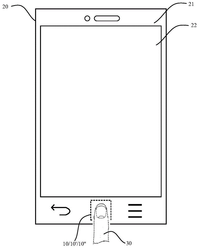
[0061] First, see figure 1 , figure 1 It is a top view of an embodiment of a mobile terminal according to the present invention. As shown in the figure, the mobile terminal described now includes a casing 20, a touch screen 21 and a liquid crystal display 22. The touch screen 21 includes a fingerprint sensor module 10 / 10' in addition to a touch-sensitive sensor film 23 and a touch cover 100. / 10".

[0062] The liquid crystal display 22 is covered u...


PUM


Abstract

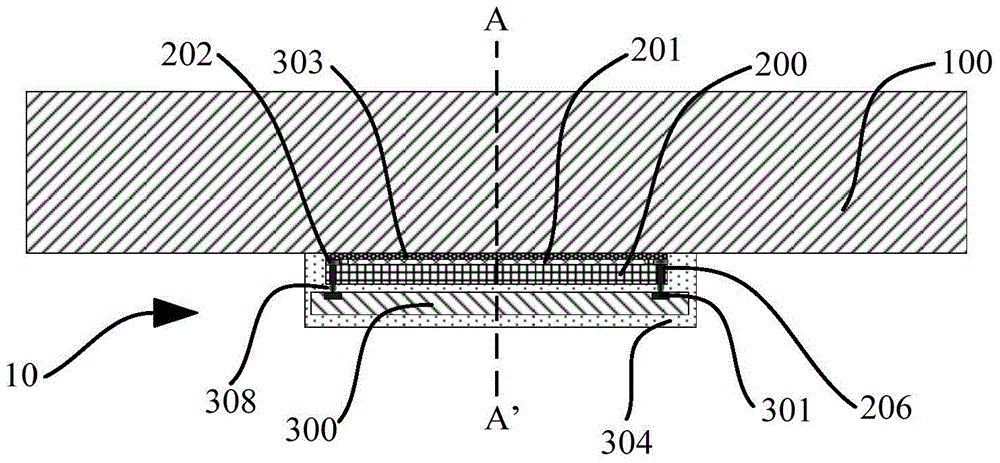
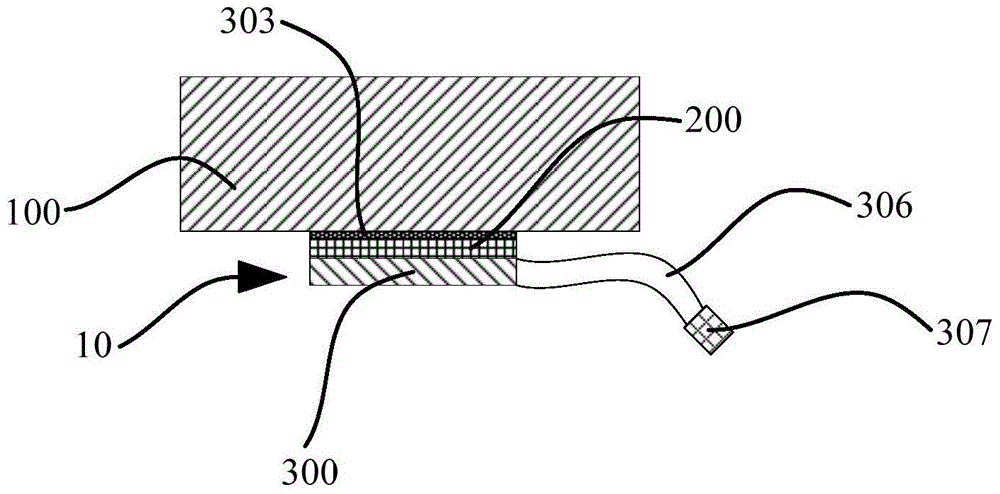
The present invention provides a mobile terminal with a fingerprint sensor packaging structure and a preparation method thereof. A fingerprint sensor assembly in the mobile terminal comprises two independent portions. The first portion is a sensor injection-molded part, which comprises a semiconductor sensor die and a sensing pixel array on the surface of the semiconductor sensor die, a base which is used for bearing the semiconductor sensor die and is electrically connected with pins of the sensor die, a bonding lead used for electrically connecting the pins of the sensor die and base pins, and an injection-molded material wrapping the sensor die (including the sensing pixel array on the surface), the bonding lead and the base. The second portion comprises a substrate which is used for bearing the sensor injection-molded part and is electrically connected with the sensor injection-molded part, a connector connected with the substrate, and a metal frame embedded to the periphery of the surface of the sensor injection-molded part. According to the fingerprint sensor assembly of the mobile terminal, size of a fingerprint sensor module can be largely reduced, and the fingerprint sensor assembly is especially suitable for a mobile terminal or device having severe requirements on spatial scale.

Description

technical field [0001] The present invention relates to the field of semiconductor packaging, in particular to a capacitive semiconductor fingerprint sensor packaging technology and related methods, and more particularly, to a mobile terminal with a fingerprint sensor packaging structure and a preparation method thereof. Background technique [0002] In recent years, with the rise of Apple's iphone5S fingerprint recognition device TouchID, there has been a wave of fingerprint recognition in the field of smart phones. [0003] However, the fingerprint identification solution in the prior art needs to install a fingerprint identification component in a groove on the front or back of the mobile phone casing, so that the collection surface of the fingerprint identification component is exposed, so as to be in contact with the finger. The slotting scheme of the casing, especially the front panel needs to open a hole in the touch screen, which not only increases the process steps ...

Claims


Application Information

Patent Timeline
IPC IPC(8): G06F1/16G06K9/00
CPCG06F1/1684G06V40/1306
Inventor 吴磊黄昊徐启波
Owner SHANGHAI FINGER TECH CO LTD
Learn More