LED (Light Emitting Diode) epitaxial structure with P (Positive) type superlattice and preparation method thereof

An epitaxial structure and superlattice technology, applied in electrical components, circuits, semiconductor devices, etc., can solve the problems of low hole concentration, low luminous brightness of LED chips, low hole injection efficiency, etc., and achieve simple process steps, Block electron overflow and improve the effect of horizontal expansion

Active Publication Date: 2013-04-17
XIANGNENG HUALEI OPTOELECTRONICS
View PDF3 Cites 40 Cited by
  • Summary
  • Abstract
  • Description
  • Claims
  • Application Information

AI Technical Summary

Problems solved by technology

[0005] The purpose of the present invention is to provide an LED epitaxial structure with a P-type superlattice and a preparation method thereof that can bind holes and increase the brightness of the chip by increasing the hole concentration, so as to solve the problem of the hole concentration of traditional PAIGaN and LTP. Not high, the hole injection efficiency is low, and the technical problems of the low brightness of the LED chip

Method used


Image

  • LED (Light Emitting Diode) epitaxial structure with P (Positive) type superlattice and preparation method thereof
  • LED (Light Emitting Diode) epitaxial structure with P (Positive) type superlattice and preparation method thereof
  • LED (Light Emitting Diode) epitaxial structure with P (Positive) type superlattice and preparation method thereof

Examples


Embodiment 1 and comparative example 1

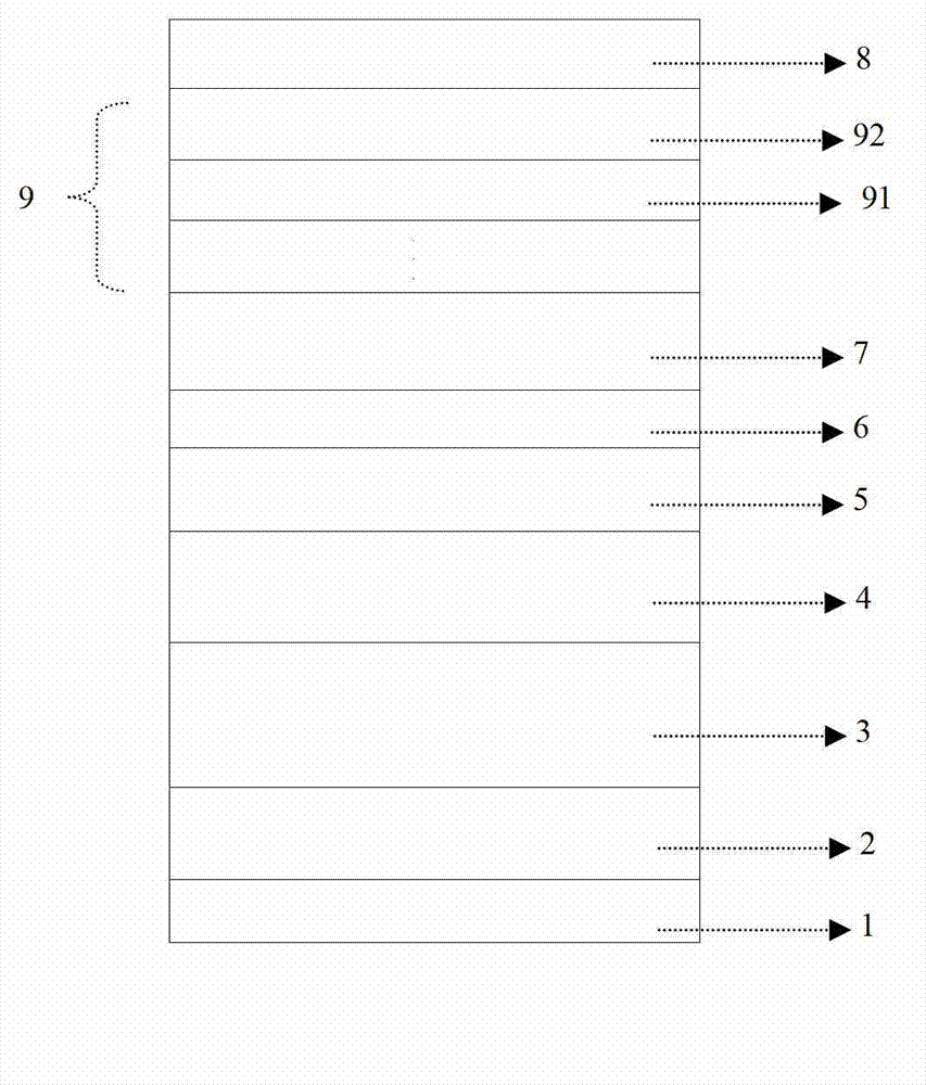
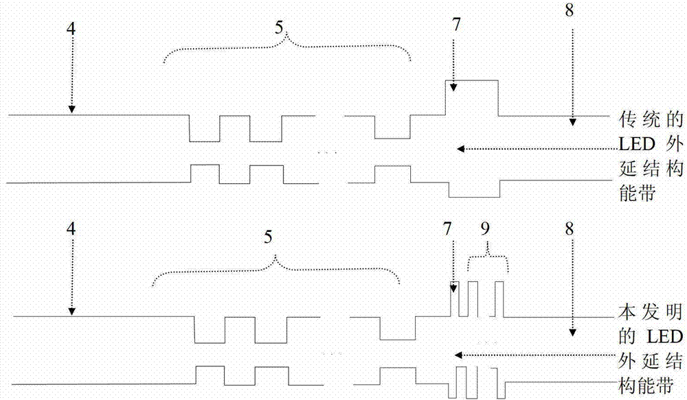
[0097] The process parameters of Step S206 and Step S207 of Example 1, and the process parameters of Step S206 of Comparative Example 1 are shown in Table 1. And the thickness of the PAlGaN (P-type AlGaN electron blocking layer 7) grown in Example 1 is 30nm, and the P-type superlattice 9 consists of two periods of PInGaN potential well layer 91 with a thickness of 5nm and a PAlGaN barrier with a thickness of 5nm The layers 92 are formed by periodically overlapping each other. The thickness of the PAIGaN (P-type AlGaN electron blocking layer 7 ) grown in Comparative Example 1 was 50 nm.

[0098] Step S206 and step S207 of the embodiment 1 of table 1, and the processing parameters of the step S206 of the comparative example 1

[0099]

[0100] In Table 1, each source gas is fed at the same time, and none indicates that no gas is fed during growth.

[0101] The epitaxial wafers obtained in embodiment 1 and comparative example 1 are carried out C-V test respectively, obtain as ...

Embodiment 2 and comparative example 2

[0106] The process parameters of Step S206 and Step S207 of Example 2, and the process parameters of Step S206 of Comparative Example 2 are shown in Table 2. And the thickness of the PAlGaN (P-type AlGaN electron blocking layer 7) grown in Example 2 is 32nm, and the P-type superlattice 9 consists of 3 periods of PInGaN potential well layers 91 with a thickness of 3nm and a PAlGaN barrier with a thickness of 3nm The layers 92 are formed by periodically overlapping each other. The thickness of the PAIGaN (P-type AlGaN electron blocking layer 7 ) grown in Comparative Example 2 was 50 nm.

[0107] Step S206 and step S207 of table 2 embodiment 2, and the process parameter of step S206 of comparative example 2

[0108]

[0109] In Table 2: all source gases are fed at the same time, and none means that they are not fed during growth.

[0110] The epitaxial wafers obtained in Example 2 and Comparative Example 2 were made into chips of 10mil*23mil and 45mil*45mil in the same chip ...

Embodiment 3

[0114] The process parameters of Step S206 and Step S207 of Example 3 are shown in Table 3. And the thickness of the PAlGaN (P-type AlGaN electron blocking layer 7) grown in Example 3 is 36nm, and the P-type superlattice 9 consists of two periods of PInGaN potential well layer 91 with a thickness of 4nm and a PAlGaN barrier with a thickness of 4nm The layers 92 are formed by periodically overlapping each other.

[0115] Step S206 of the embodiment 3 of table 3 and the process parameter of step S207

[0116]

[0117] In Table 3: all source gases are fed at the same time, and none means that they are not fed during growth.


PUM


Abstract

The invention discloses an LED (Light Emitting Diode) epitaxial structure with a P (Positive) type superlattice and a preparation method thereof. The epitaxial structure comprises a substrate, wherein a GaN (Gallium Nitride) buffer layer, an undoped GaN layer, an n (negative) type GaN layer, a multi-quantum well luminous layer, a first P type GaN layer, a P type AlGaN (Aluminium Gallium Nitride) electronic blocking layer and a second P type GaN layer are sequentially arranged on the substrate from bottom to top, and the P type superlattice formed by a PInGaN (P type Indium Gallium Nitride) potential well layer and a PAlGaN potential barrier layer in a periodic interactive overlapping way is arranged between the P type AlGaN electronic blocking layer and the second P type GaN layer. The PInGaN potential well layer in the P type superlattice generates and constrains a great number of holes for the formation of a two-dimensional hole high-density state; the PAlGaN potential barrier layer hinders the escape of the holes; in such a way, the transverse spreading of the holes is improved, the electron overflow can be prevented, the hole injection efficiency is increased and the electron and hole recombination probability is improved; and therefore, the brightness of a chip can be improved by 5-10%.

Description

technical field [0001] The invention relates to the technical field of semiconductors, in particular to an LED epitaxial structure with a P-type superlattice and a preparation method thereof. Background technique [0002] Due to its excellent characteristics, GaN has become an important material for manufacturing light-emitting devices, high-temperature and high-power devices and ultraviolet detectors. P-type doping is an essential part of manufacturing GaN devices, so it has attracted the attention of many research groups. Due to the passivation of Mg, the resistivity of untreated GaN:Mg is as high as 10Q·cm, and Mg must be activated after growth to obtain P-type GaN that can be applied to devices. In 1989 H. Amano made a major breakthrough in P-type. He used low-energy electron beam radiation (IEEBI) to process Mg-doped GaN and obtained low-resistance P-type GaN. In 1991, S. Nakamura and others invented the rapid thermal annealing method (Rapid Thermal Annealing), and ...

Claims


Application Information

Patent Timeline
Patent Type & Authority Applications(China)
IPC IPC(8): H01L33/06H01L33/14H01L33/00
Inventor 张宇
Owner XIANGNENG HUALEI OPTOELECTRONICS
Why Eureka
Try Eureka