Battery temperature control system for vehicles and use method therefor

A battery temperature control and battery temperature technology, applied in secondary batteries, circuits, electrical components, etc., can solve the problems of water temperature control lag, reduce temperature control effect, etc., to increase heat dissipation, speed up fan speed, and widen the control range Effect

Active Publication Date: 2016-06-15
DONGFENG COMML VEHICLE CO LTD
View PDF6 Cites 23 Cited by
  • Summary
  • Abstract
  • Description
  • Claims
  • Application Information

AI Technical Summary

Problems solved by technology

Although this design can liquid-cool the battery pack through the radiator, the effect is better than air cooling, but the basis for determining the degree of cooling is the temperature difference between the detected temperature of the cooling water in the cooling water tank and the set temperature, and the detected temperature is higher than the set temperature. Then adjust the flow rate of the external circulating water to control the cooling water temperature. There is a certain lag in the water temperature control, which will reduce the temperature control effect.

Method used


Image

  • Battery temperature control system for vehicles and use method therefor
  • Battery temperature control system for vehicles and use method therefor

Examples


Embodiment 1

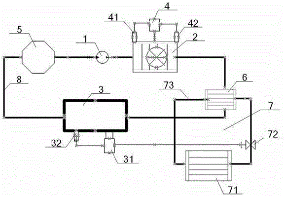
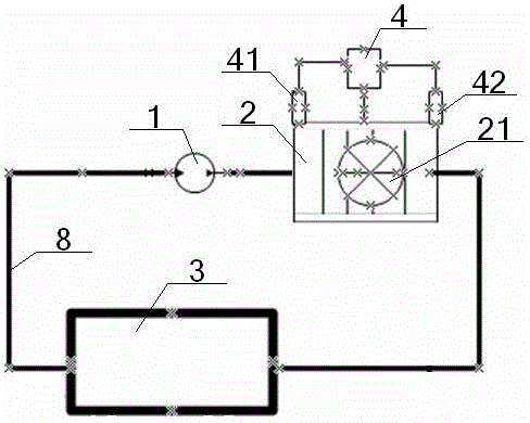
[0050] Structurally: see figure 1 and figure 2 , a vehicle battery temperature control system and its use method, comprising a water pump 1, a radiator 2, a battery pack 3, a water inlet temperature sensor 41, a water outlet temperature sensor 42 and a radiator controller 4, the outlet of the water pump 1 The water port communicates with the water inlet of the radiator 2, the water outlet of the radiator 2 communicates with the water inlet of the battery pack 3, the water outlet of the battery pack 3 communicates with the water inlet of the water pump 1, and the water inlet temperature sensor 41 is near the inlet of the radiator 2. The water outlet is set, the water outlet temperature sensor 42 is set near the water outlet of the radiator 2, the water inlet temperature sensor 41, and the water outlet temperature sensor 42 are all connected with the signal input end of the radiator controller 4, and the signal output of the radiator controller 4 The end is connected to the ra...

Embodiment 2

[0053] Basic content is the same as embodiment 1, the difference is:

[0054] Structurally: the vehicle battery temperature control system further includes a driving motor 5 , the water inlet of the driving motor 5 communicates with the water outlet of the battery pack 3 , and the water outlet of the driving motor 5 communicates with the water inlet of the water pump 1 .

Embodiment 3

[0056] Basic content is the same as embodiment 1, the difference is:

[0057] Structurally: the radiator 2 is provided with a cooling fan 21 .

[0058] In terms of method: the radiator controller 4 controls the radiator 2 to turn on the heat dissipation means: the radiator controller 4 controls the cooling fan 21 to start rotating to dissipate heat; the radiator controller 4 controls the radiator 2 to increase the cooling power. Refers to: the radiator controller 4 controls the cooling fan 21 to increase its rotating speed, so as to increase the cooling power.


PUM


Abstract

The invention discloses a battery temperature control system for vehicles. The battery temperature control system comprises a water pump, a radiator and a battery pack that can are connected in series in sequence to form a cooling loop, wherein a liquid-liquid heat exchanger with an additional heating apparatus can be arranged between the radiator and the battery pack; when the battery temperature control system is in use, the radiator controls the radiating power according to the instantaneous temperatures of the water inlet and water outlet of the radiator so as to cool the battery pack; and a battery controller also can control the heating apparatus according to the instantaneous temperature of the battery pack to heat the cooling water flowing through the liquid-liquid heat exchanger so as to further heat the battery pack. Due to the design, the battery temperature control system is relatively high in regulation and control capability, and capable of heating and cooling the battery pack and realizing temperature control in time, and relatively high in energy utilization ratio.

Description

technical field [0001] The invention relates to a vehicle battery temperature control device, which belongs to the field of automobiles, in particular to a vehicle battery temperature control system and a method for using the same, which is specifically suitable for increasing the temperature rise function on the basis of improving the timeliness of temperature control. Background technique [0002] With the vigorous promotion of energy conservation and emission reduction policies, the new energy vehicle business has ushered in unprecedented development opportunities. However, there are still deficiencies in the development and design of some key components, which need to be improved, including batteries, one of the power sources of new energy vehicles. Generally, the ideal operating temperature of a power battery is between 25°C and 40°C. The efficiency of traditional air cooling is very low, and it is difficult to meet the requirements of the battery operating temperature ...

Claims


Application Information

Patent Timeline
Patent Type & Authority Applications(China)
IPC IPC(8): H01M10/617H01M10/625H01M10/637H01M10/6568H01M10/6563
CPCH01M10/617H01M10/625H01M10/637H01M10/6563H01M10/6568Y02E60/10
Inventor 王丹丹宋宏贵钟亮刘金鑫
Owner DONGFENG COMML VEHICLE CO LTD
Why Eureka
Try Eureka