A differential generator stator for automobiles

A technology for generator stators and automobiles, applied in electric components, electromechanical devices, electrical components, etc., can solve problems affecting motor operation, mechanical and electronic faults, etc., and achieve the effect of improving efficiency, reducing heat generation, and reducing motor loss.

Active Publication Date: 2018-12-11
HUAXING VEHICLE ELECTRICAL EQUIP FACTORY CIXI CITY
View PDF6 Cites 0 Cited by
  • Summary
  • Abstract
  • Description
  • Claims
  • Application Information

AI Technical Summary

Problems solved by technology

Furthermore, the use of precision instrument control can only be used when the waterproof effect has been tested for reliability, otherwise it will cause serious mechanical and electronic failures and affect the operation of the motor

Method used


Image

  • A differential generator stator for automobiles

Examples


Embodiment 1

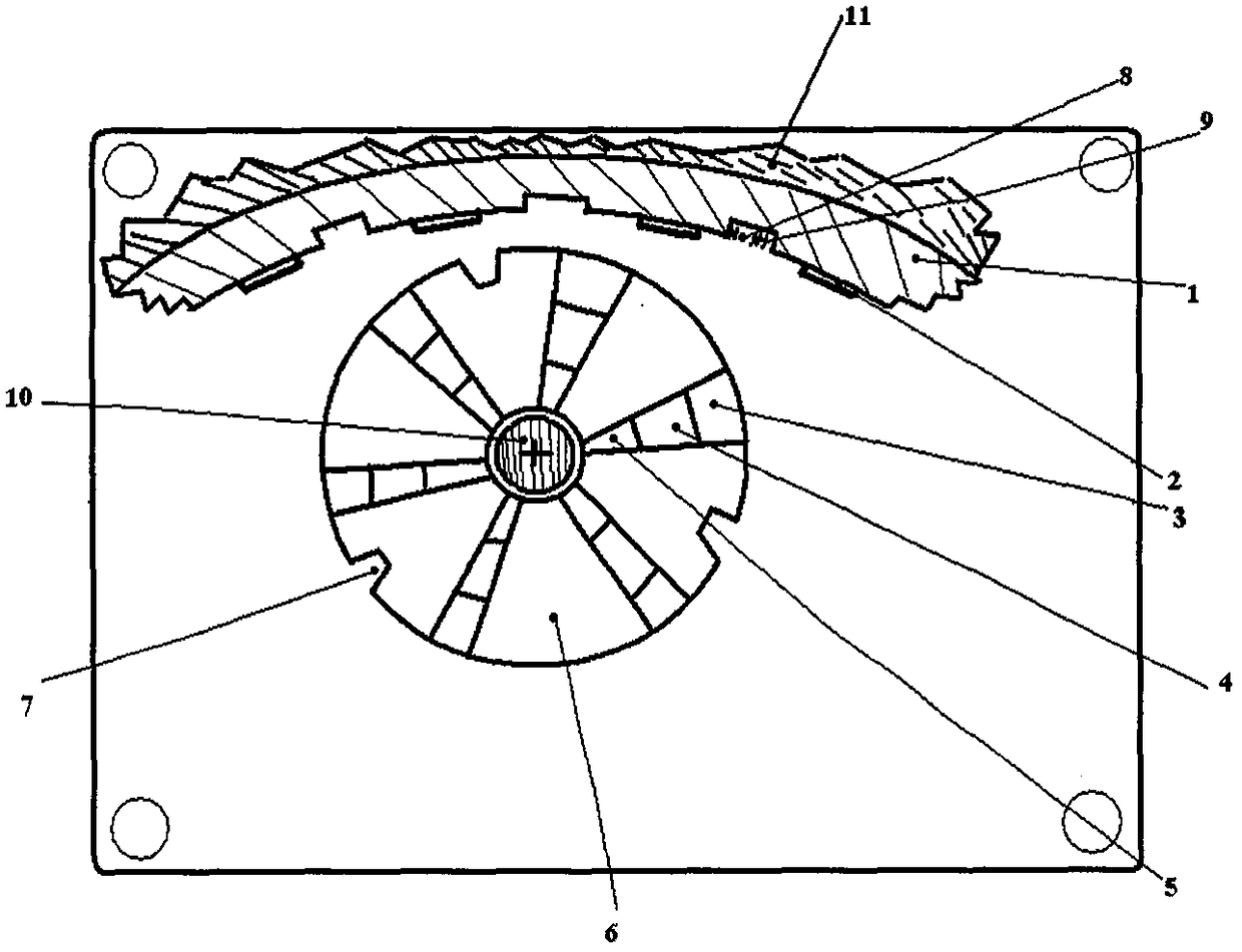
[0015] refer to figure 1 , a differential generator stator for automobiles, a conjugate plate is installed in the motor housing, a stator 11 is provided on the conjugate plate, the stator 11 is a circular structure, and the stator core 1 is located on the inner side wall of the stator 11. The stator core 1 is provided with 12 pairs of phase grooves 8, and the stator main winding 9 is placed in the phase grooves 8. A number of differential magnetic steels are evenly inlaid on the stator core 1. Bar 2, every two magnetic steel bars 2 are separated by one of the grooves 8, the center position of the rotor 6 matched with the stator 11 is the rotor shaft 10, and differential The groove 7, the number of the phase groove 8 is twice that of the differential groove 7, a number of three-stage secondary coil windings are arranged on the rotor 6, the primary secondary coil winding 3, the secondary secondary coil winding 4 The primary secondary coil winding 3 and the secondary secondary c...

Embodiment 2

[0017] refer to figure 1 , a differential generator stator for automobiles, a conjugate plate is installed in the motor housing, a stator 11 is provided on the conjugate plate, the stator 11 is a circular structure, and the stator core 1 is located on the inner side wall of the stator 11. The stator core 1 is provided with 14 pairs of phase grooves 8, and the stator main winding 9 is placed in the phase grooves 8. A number of differential magnetic steels are evenly inlaid on the stator core 1. Bar 2, every two magnetic steel bars 2 are separated by one of the grooves 8, the center position of the rotor 6 matched with the stator 11 is the rotor shaft 10, and differential The groove 7, the number of the phase groove 8 is three times that of the differential groove 7, a number of three-stage secondary coil windings are arranged on the rotor 6, the primary secondary coil winding 3, the secondary secondary coil winding 4 The primary secondary coil winding 3 and the secondary secon...


PUM


Abstract

The invention relates to a differential generator stator for a vehicle. A conjugate board (4) is arranged in a motor shell; a stator (11) is arranged on the conjugate board (4) and is in a round structure; a stator core (1) is located on the inner side wall of the stator (11); phase grooves (8) are arranged on the stator core (1); a stator main winding (9) is arranged in each phase groove (8); the stator core (1) is evenly inlaid with a plurality of differential magnetic steel bars (2); each two magnetic steel bars (2) are partitioned by one groove (8); a rotor rotating shaft (10) is arranged at the center position of a rotor (6) matched with the stator (11); differential grooves (7) are evenly arranged on the rotor (6); the quantity of the phase grooves (8) is 2-3 times that of the differential grooves (7); and a plurality of three-stage secondary coil windings are arranged on the rotor (6).

Description

technical field [0001] The invention relates to the field of motors, and in particular provides a differential generator stator for automobiles. Background technique [0002] The efficiency of the motor stator in the prior art is not high, and it is easy to generate heat. The heat accumulation is serious and the heat cannot be dissipated as soon as possible. For example, CN203911712 discloses a high-efficiency motor for electric vehicles, including a motor shaft, and an inner stator is fixed in the middle of the motor shaft , the outer circumference side of the inner stator is surrounded by an outer rotor, the inner stator is provided with a stator core, and the stator core is uniformly distributed along the circumferential direction with stator core slots, and iron cores are embedded in the iron core slots, so Coil windings are wound on the inner stator, and magnetic steel sheets are evenly distributed on the inner circumference side of the outer rotor to form a magnetic st...

Claims


Application Information

Patent Timeline
Patent Type & Authority Patents(China)
IPC IPC(8): H02K1/16H02K1/17H02K3/28H02K3/51H02K5/18
CPCH02K1/16H02K1/17H02K3/28H02K3/51H02K5/18H02K2203/06H02K2213/03
Inventor 叶建强
Owner HUAXING VEHICLE ELECTRICAL EQUIP FACTORY CIXI CITY
Why Eureka
Try Eureka