
Novel energy-saving induction voltage regulator

An induction voltage regulator, energy-saving technology, applied in the direction of control of mechanical energy, casing/cover/support, electrical components, etc., can solve the problems of difficult heat discharge, high power consumption of the voltage regulator, and incapable of voltage regulation control. To prevent frequent overcurrent, save power consumption, and ensure normal operation

Inactive Publication Date: 2016-06-15
YANGZHOU XINYUAN ELECTRIC
View PDF0 Cites 0 Cited by
  • Summary
  • Abstract
  • Description
  • Claims
  • Application Information

AI Technical Summary

Problems solved by technology

[0002] The voltage regulator is widely used. It adjusts the angular displacement of the rotor to change the phase (three-phase) and amplitude (single-phase) of the induced potential of the stator or rotor winding to achieve the purpose of non-contact voltage regulation. When the voltage regulator is working, it often encounters the phenomenon that it is difficult to discharge heat. Once the internal temperature is high, it will affect the normal operation of the internal parts of the voltage regulator, and it will not be able to perform stable voltage regulation control. There are also some voltage regulators The power consumption is relatively large and consumes a lot of electric energy. Some electric energy does not need to be consumed and cannot play a role in saving electric energy consumption. This results in a large voltage load and affects the normal operation of other working electrical components.

Method used


Image

  • Novel energy-saving induction voltage regulator

Examples


Embodiment Construction

[0010] The present invention will be further described below in conjunction with the accompanying drawings.

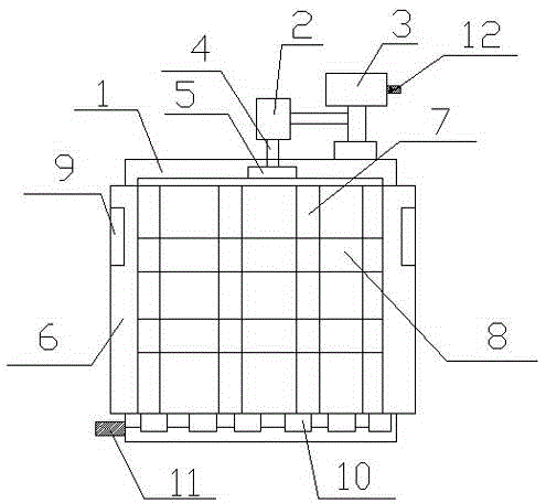
[0011] A new type of energy-saving induction voltage regulator, including a power transmission device and a main body of the voltage regulator 1, the power transmission device is the top of the main body of the voltage regulator, the power transmission device is composed of a reducer 2 and a motor 3, the reducer 2 and the motor 3 The lower part of the reducer 2 is provided with a rotating shaft 4, the rotating shaft 4 is connected with the rotor shaft 5, and the rotating shaft 4 drives the rotor shaft 5 to move. The casing 6 is provided with rotor windings 7 and stator windings 8. The casing 6 is provided with heat dissipation components 9. The heat dissipation components 9 are heat dissipation windows. Rectangular structure, the heat dissipation blade 10 is a movable structure, the heat dissipation blade 10 can be turned up and down, there is a turning part 11 beside ...


PUM


Abstract

The invention provides a novel energy-saving induction voltage regulator, which comprises a power transmission device and a voltage regulator main body, wherein the power transmission device is the top part of the voltage regulator main body and comprises a speed reducer and a motor; a rotating shaft is arranged at the lower part of the speed reducer; the rotating shaft drives a rotor shaft to move; the voltage regulator main body comprises a shell, rotor windings and stator windings; and the rotor windings and the stator windings are arranged in the shell. Cooling components are arranged on the shell and can timely send out the heat in the voltage regulator, so that a moderate temperature in the voltage regulator is ensured. Cooling fins are arranged at the bottom part, and can transmit the heat at the bottom part; the turnover angle of the cooling fins can be controlled through a turnover component; and selective heat emission can be carried out according to the heat in the voltage regulator and the external environment, so that a relatively large temperature difference between the inside and the outside is avoided. A frequency converter is arranged next to the motor, and the motor can carry out variable frequency operation, so that power consumption can be reduced when the voltage regulator works.

Description

technical field [0001] The invention relates to a voltage regulator, in particular to a novel energy-saving induction voltage regulator. Background technique [0002] The voltage regulator is widely used. It adjusts the angular displacement of the rotor to change the phase (three-phase) and amplitude (single-phase) of the induced potential of the stator or rotor winding to achieve the purpose of non-contact voltage regulation. When the voltage regulator is working, it often encounters the phenomenon that it is difficult to discharge heat. Once the internal temperature is high, it will affect the normal operation of the internal parts of the voltage regulator, and it will not be able to perform stable voltage regulation control. There are also some voltage regulators It consumes a lot of power and consumes a lot of power. Some of the power does not need to be consumed, and it cannot save power consumption. It causes a large voltage load and affects the normal operation of oth...

Claims


Application Information

Patent Timeline
IPC IPC(8): H02K7/10H02K5/04H02K5/20H02K11/00
Inventor 张炳生李如林汤爱平李锐海朱烨孙夏青邹林张贵峰郝爽王颂廖新征
Owner YANGZHOU XINYUAN ELECTRIC
Learn More