
Motor controller

A technology of motor control and control unit, which is applied in the direction of motor control, control system, electrical components, etc., and can solve problems such as difficulty in shortening cycle time

Active Publication Date: 2016-06-15
SANYO DENKI CO LTD
View PDF8 Cites 0 Cited by
  • Summary
  • Abstract
  • Description
  • Claims
  • Application Information

AI Technical Summary

Problems solved by technology

Therefore, it is difficult to shorten the cycle time

Method used


Image

  • Motor controller
  • Motor controller
  • Motor controller

Examples


Embodiment Construction

[0029] In the following detailed description, for purposes of explanation, numerous specific details are set forth in order to provide a thorough understanding of the disclosed embodiments. It may be evident, however, that one or more embodiments may be practiced without these specific details. In other instances, well-known structures and devices are shown schematically in order to simplify the drawings.

[0030] Embodiments of the present invention will be described below.

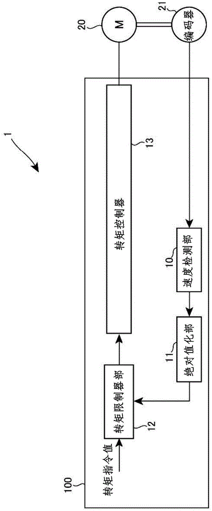
[0031] figure 1 It is an explanatory diagram of the motor control device according to the embodiment of the present invention.

[0032] The motor control device 1 has a control unit 100 , a motor 20 and an encoder 21 . The control unit 100 has a speed detection unit 10 , an absolute value conversion unit 11 , a torque limiter unit 12 , and a torque controller 13 . The motor control device 1 receives power supply from an external power source.

[0033] The control unit 100 drives the motor 20 . The ...


PUM


Abstract

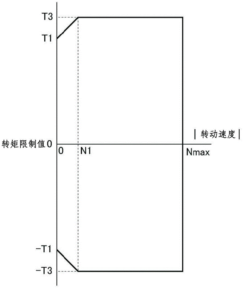
The invention provides a motor controller which can suppress the shortening of the power cycle life and the thermal cycle life of electrical semiconductor elements, and increase the maximum current of the motor controller and the maximum torque of the motor. The motor controller comprises a motor and a controller part which is used for controlling the motor. The controller part increases the maximum absolute value of the motor torque with the increasing of velocity absolute value when the absolute value of the motor velocity is lower than a specified value under instaneous driving of the motor.

Description

technical field [0001] Embodiments of the present invention relate to a motor control device. Background technique [0002] In recent years, in order to reduce the manufacturing cost of a mechanical device including a motor, shortening of cycle time is required. In order to shorten the cycle time, it is possible, for example, to increase the maximum speed of the electric motor driving the mechanism. However, the maximum speed of the motor is limited by the power transmission mechanism. Therefore, increasing the maximum speed of the motor is limited. [0003] On the other hand, in order to shorten the cycle time, it is also conceivable to shorten the acceleration and deceleration time of the motor. This can be achieved, for example, by increasing the maximum torque of the electric motor. In order to increase the maximum torque of the motor, for example, increase the maximum output current of the motor control device. However, the power semiconductor element used in the i...

Claims


Application Information

Patent Timeline
Patent Type & Authority Applications(China)
IPC IPC(8): H02P29/00
Inventor 井出勇治小山雅久小市伸太郎
Owner SANYO DENKI CO LTD
Learn More