Maximum brightness enhancement module, thyristor dimming led drive circuit and system

A technology of LED driving and maximum brightness, applied in the direction of lamp circuit layout, light source, electric light source, etc., can solve the problems of loss of LED drive circuit efficiency, temperature rise, high power consumption, etc., to improve efficiency and system reliability, and improve the maximum The effect of current

Active Publication Date: 2015-10-07
SHANGHAI BRIGHT POWER SEMICONDUCTOR CO LTD
View PDF7 Cites 0 Cited by
  • Summary
  • Abstract
  • Description
  • Claims
  • Application Information

AI Technical Summary

Problems solved by technology

[0005] 2) The power consumption of the bleeder resistor R1 and the bleeder switch M2 is high, which leads to loss of LED drive circuit efficiency and high temperature rise, which reduces system reliability

Method used


Image

  • Maximum brightness enhancement module, thyristor dimming led drive circuit and system
  • Maximum brightness enhancement module, thyristor dimming led drive circuit and system
  • Maximum brightness enhancement module, thyristor dimming led drive circuit and system

Examples


Embodiment Construction

[0018] The implementation of the thyristor dimming LED drive circuit and system provided by the present invention will be described in detail below in conjunction with the accompanying drawings.

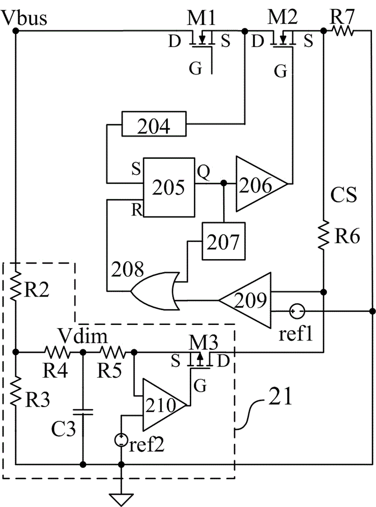
[0019] refer to figure 2 , a structural schematic diagram of the thyristor dimming LED drive circuit according to the present invention, the drive circuit includes: a second MOS transistor M2, a peak current comparator 209, a feedforward resistor R6, a reference voltage source ref1 and A maximum brightness enhancement module 21 .

[0020] The maximum brightness enhancement module 21 includes: an operational amplifier 210, a first MOS transistor M3, a reference voltage source ref2, a voltage division processing unit and a filter unit.

[0021] The voltage division processing unit receives and processes an external voltage signal Vbus with a positive amplitude. As a preferred embodiment, the voltage division processing unit includes an upper voltage divider resistor R2 and a lower v...


PUM


Abstract

The invention discloses a silicon controlled light-dimmer LED driving circuit. A drain electrode of a second MOS transistor is connected with a source electrode of a power switch MOS transistor, a source electrode of the second MOS transistor is connected with a sampling resistor, the output end of a largest brightness lifting module is electrically connected with the first input end of a peak value current comparator and a feedforward resistor through a drain electrode of a first MOS transistor in the largest brightness lifting module, current signals output by the first MOS transistor pass through the feedforward resistor to generate direct-current bias voltages, the first input end of the peak value current comparator is electrically connected with the sampling resistor through the feedforward resistor, the second input end of the peak value current comparator is electrically connected with the output end of a reference voltage source, the output end of the peak value current comparator is coupled to a grid electrode of the second MOS transistor, and the peak value current comparator is used for comparing the sum of the voltage amplitude of the feedforward resistor and the voltage amplitude of the sampling resistor with a voltage threshold value of the reference voltage source, and controls the second MOS transistor to be switched on and off. When a driving circuit is connected with a silicon controlled light dimmer, the largest current is improved through the largest brightness lifting module.

Description

technical field [0001] The invention relates to the field of LED driving, in particular to a thyristor dimming LED driving circuit and system with maximum brightness improvement. Background technique [0002] see figure 1 , a simplified schematic diagram of a prior art thyristor dimming LED drive circuit. Such as figure 1 As shown, an input AC power source 101 is connected in series with a thyristor dimmer 102 , and then connected to two input terminals of a rectifier bridge 103 . The rectifier bridge 103 rectifies the alternating current and filters it through the capacitor C1 to generate a rectified sinusoidal voltage. The resistor R4 and the capacitor C2 generate a low-voltage direct current to activate the control chip 104 . The transformer T1 has three windings, including a primary winding T11 connected between the capacitor C1 and the drain of the power switch MOS transistor M1; a secondary winding T12 connected between the freewheeling diode D1 and the secondary o...

Claims


Application Information

Patent Timeline
Patent Type & Authority Patents(China)
IPC IPC(8): H05B37/02
Inventor 杜磊宗强孙顺根
Owner SHANGHAI BRIGHT POWER SEMICONDUCTOR CO LTD
Why Eureka
Try Eureka