Spatial data security control system based on access mode protection

A technology of spatial data and security control, applied in transmission systems, electrical components, etc., can solve problems such as reducing the degree of information disclosure

Inactive Publication Date: 2016-06-15
NORTH CHINA UNIV OF WATER RESOURCES & ELECTRIC POWER
6 Cites 3 Cited by

AI-Extracted Technical Summary

Problems solved by technology

[0017] The purpose of the present invention is to provide a spatial data security control system based on access mode protection, which aims to solve the problems of ...

Method used

Another object of the present invention is to provide a kind of memory configurable energy-saving scheduling method of the spatial data security control system based on access mode protection, the method of configurable energy-saving scheduling includes cache high-speed memory for multi-core embedded systems Application performance monitor parameters are set, multi-core embedded system cache optimization configuration research method is used to optimize and improve the algorithm, and the most ...

Abstract

The invention discloses a spatial data security control system based on access mode protection. The spatial data security control system comprises an authorization server, a service provider, a service requester, a radio-frequency identification (RFID) reader and an RFID tag; an authorization server module provided by the invention comprises three parts including a key library, an attributive library and a strategy library; an authorized public key of the service requester and an encrypted private key of the service provider are stored in the key library; attribute information of all parties of the system is stored in the attributive library; a decision strategy of the system is stored in the strategy library; the key library, the attributive library and the strategy library each have the basic functions of increasing, deleting, searching and backing up stored information and the like; requirements on an information source in an access control process are effectively satisfied; a strategy is implied in the encrypted secrete key in the encryption processing operation of the service provider; an access control rule to resource setting is contained; and simultaneously, the data security is also effectively protected.

Application Domain

Transmission

Technology Topic

Radio frequencyService provider +9

Image

  • Spatial data security control system based on access mode protection
  • Spatial data security control system based on access mode protection
  • Spatial data security control system based on access mode protection

Examples

  • Experimental program(1)

Example Embodiment

[0095] In order to make the object, technical solution and advantages of the present invention more clear, the present invention will be further described in detail below in conjunction with the examples. It should be understood that the specific embodiments described here are only used to explain the present invention, not to limit the present invention.
[0096] The application principle of the present invention will be further described below in conjunction with the accompanying drawings and specific embodiments.
[0097] The application principle of the present invention will be further described below in conjunction with the accompanying drawings.
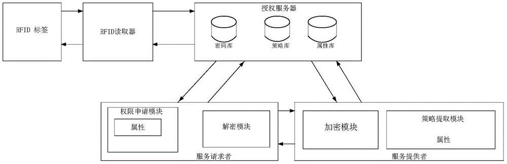
[0098] like figure 1 : a kind of space data security control system based on access mode protection, including authorization server, service provider, service requester, radio frequency identification (RFID) reader and RFID label; Described authorization server is connected with service requester and service provider respectively data exchange between the service requester and the service provider;
[0099] The radio frequency identification (RFID) reader includes electronic components that enable the RFID reader to generate a radio frequency (RF) field and exchange data with an RFID device located within the RF field; the RFID tag is signally connected to the An RFID reader in signal connection with the authorization server.
[0100] The authorization server authorizes and assigns the service requester, provides both public and private key distribution to the service requester and the service provider, and integrates the security domain access control process and the privacy protection mechanism; the authorization server includes a key storehouse, Attribute library and policy library.
[0101] The key storehouse is used to save the authorized public key of the service requester and the encrypted private key of the service provider; the attribute storehouse stores the attribute information of the service provider module and the service requester module; the policy storehouse is used for storing system decision-making strategy; the key storehouse, attribute storehouse, and policy storehouse all have the functions of adding, deleting, searching, and backing up stored information.
[0102] The service provider is a passive entity that accepts the subject's access according to the stipulations of the permission set, and the service provider includes a policy extraction module and an encryption module;
[0103]The policy extraction module extracts policies by sending object attributes; the encryption module is responsible for completing the encryption of information, including access control policies set for resources.
[0104] The service requester is an active entity that has permission to use the service provider, including an authorization application module and a decryption module;
[0105] The authorization application module applies for permission by sending the subject attribute; the decryption module is responsible for completing the decryption of information.
[0106] The RFID tag includes an antenna and a memory, the RFID tag is configured to have an encrypted private key written to its memory by a near field communication (NFC) device, and wherein the RFID tag is further configured to pass the NFC device The RFID reader is passed the encrypted private key written to its memory.
[0107] The RFID reader further includes a casing, and wherein the RFID tag is located in the casing, and the encrypted private key written to the memory of the RFID tag is stored therein and deleted when a predetermined number is reached.
[0108] The RFID reading also includes an antenna, the center of the antenna of the RFID tag is offset relative to the center of the antenna of the RFID reader, the RFID reader is further configured to instruct the control circuit of the RFID tag to An antenna of the RFID tag is detached from an integrated circuit (IC) of the RFID tag for a predetermined amount of time, and the RFID reader provides power to the RFID tag via at least one of the RF field and a service interface.
[0109] The near field communication (NFC) device includes a processor, the processor includes a memory of an NFC module and an NFC interface, and the NFC module is configured to determine that the NFC device is located within a radio frequency identification (RFID) reader. and in response to determining that the NFC device is within the RF field generated by the RFID reader, writes an access control encrypted private key to the RFID tag that is also within the RF field. key, so that the RFID tag can transmit the access control encryption private key to the RFID reader on behalf of the NFC device.
[0110] The NFC device further includes a network interface enabling the NFC device to receive the access control encryption private key, and the NFC module further enables the NFC device to transmit the access control key to the RFID tag, Information can be read back from the RFID tag, the information read back from the RFID tag being transmitted to a central system via the network interface.
[0111] The application principle of the present invention will be described in detail below in conjunction with specific embodiments.
[0112] Authorization server module: The authorization server module includes three parts: key storehouse, attribute storehouse, and policy storehouse. The key store stores the authorization key of the service requester and the encryption key of the service provider. The property repository stores property information. The policy library stores the decision-making policies of the system. Based on the three decision-making factors of authorization, obligation and condition, the policy library designs a set of access control policy models in combination with continuity and variable attributes. The key storehouse, attribute storehouse, and policy storehouse all have basic functions such as adding, deleting, searching, and backing up stored information.
[0113] Service provider module: The service provider module is a passive entity (that is, an object) that accepts the subject's access according to the provisions of the permission set. The object can be a collection of information, files, records, etc. used in the workflow system, or it can be a hardware device on the network, a terminal in wireless communication, etc. The service provider module includes a policy extraction module and an encryption module. The policy extraction module performs policy extraction. The encryption module is responsible for completing the encryption of information, including access control policies set for resources.
[0114] Service Requester Module: The Service Requester Module is an active entity (ie, subject) that may have certain usage rights to the Service Provider. The meaning of subject is very broad. It can be the organization (user group) of the user, the user itself, or the computer terminal, card machine, handheld terminal (wireless) used by the user, or even an application service program or process. The service requester module includes an authorization application module and a decryption module. The authorization application module applies for permissions. Among them, the subject attribute is the attribute used in the access decision-making process, which identifies the subject's ability and characteristics, and is an important parameter in the permission decision-making process. The service requester needs to regularly or irregularly report to the authorization server through the authorization application module. Update your own attribute information. The decryption module is responsible for completing the decryption of information, which is equivalent to the consistency verification process in access control.
[0115] Privacy protection algorithm: The privacy protection algorithm completes the integration of cross-security domain access control and privacy protection mechanisms in the process of system initialization, authorization assignment, policy customization, encryption processing, message recovery and verification.
[0116] A control method for a space data security control system based on access mode protection:
[0117] (1) Privacy protection-based cross-security domain access control system initialization;
[0118] (2) The service requester sends its own identification ID to the authorization server to request authorization credentials;
[0119] (3) The authorization server analyzes the attribute set owned by the service requester according to the service requester ID;
[0120] (4) The authorization server calculates the authorized decryption key component and sends it to the service requester;
[0121] (5) The service provider sends all attribute identifiers related to the local policy to the authorization server;
[0122] (6) The authorization server calculates the encryption policy encryption key component and sends it to the service provider;
[0123] (7) The service requester initiates a service request to the service provider;
[0124] (8) The service provider calculates the authorized decryption key component of the service requester, and randomly selects intermediate variables, so that u=H3(σ,m);
[0125] (9) The service provider extracts the policy expression according to the request resource identifier, and determines the tuple number of the ciphertext;
[0126] (10) Determine the ciphertext, and send the encrypted resource response information to the service requester;
[0127] (11) The service requester extracts the policy expression from the resource response information, determines the tuple number of the ciphertext at the same time, and judges whether the first tuple number of the ciphertext belongs to the additive cyclic group;
[0128] (12) The service requester constructs the key according to the policy expression, and selects the attribute combination that meets the policy sub-items;
[0129] (13) The service requester repeats the calculation and verifies that U=uP?
[0130] (14) The service requester outputs plaintext using the decryption key component.
[0131] Wherein, in the step (1), the system initialization is completed by the authorization server, including: given the security parameter k∈Z+, input k to generate a large prime number q, and select the supersingular elliptic curve E/GF(p ), generate two groups G1 and G2 with order q through E/GF(p), G1 is an additive cyclic group, G2 is a multiplicative cyclic group, the bilinear mapping randomly selects the intermediate variable P∈G1; selects a random number.
[0132] Construct plaintext space M={0,1}n. Wherein, in the step (2), the range of the identification ID is ID∈{0,1}*; in the step (3), the attribute
[0133] A set is denoted by {a1,a2,...,am}.
[0134] In the step (4), the authorization server sends the collection to the service requester through calculation, and the collection is the authorized decryption key component distributed by the authorization server to the service requester. The owner's formulation has nothing to do with this algorithm, it is formulation: what attributes users can access to resources with what attributes, which belongs to the policy formulation category of the access control method UCON) to decrypt confidential information.
[0135] In the step (5), the attribute identifier is represented by {a1, a2, . . . , an}.
[0136] In the step (6), the authorization server sends the set to the service provider through calculation, and the set is the authorized encryption key component distributed by the authorization server to the service provider.
[0137] In the step (7), the service request is represented by , wherein SID is a resource identifier.
[0138] In the step (8), the service provider calculates the authorized decryption key component of the service requester and randomly selects the intermediate variable σ∈(0,1)n, and sets u=H3(σ,m).
[0139] In the step (9), the service provider extracts the policy expression {ai, 1∧...∧ai, m} according to the request resource identifier SID (each component of this expression refers to an attribute, representing what must have Only such combination of attributes can gain access), and the number of tuples of the ciphertext is determined for each policy expression. There are many policy expressions for each resource, and any policy expression that matches can obtain the corresponding permission. Each component of this expression refers to the corresponding ciphertext ancestor component calculated for each policy expression. All All the ciphertext ancestors calculated by the policy expression of ∆ together form the ciphertext.
[0140] In the step (10), select a positive integer to determine the ciphertext (this is a bit XOR operation), i=1,...,k, and send the encrypted resource response information to the service requester; Indicates the hash space of the hash function H3; Ploicy is the resource access strategy.
[0141] In the described step (11), the tuple number of the ciphertext C is k, and C=, when the first tuple number of the ciphertext belongs to the additive cyclic group, then Go to step (12); when the first tuple number of the ciphertext does not belong to the additive cyclic group, the ciphertext is rejected.
[0142] In the step (12), the coefficients of the attribute combination decryption key component and encryption key component of the policy subitem are represented by {a1, a2,..., am}, and the upper limit is represented by n and m, representing The number of attributes will not cause confusion, because the attributes are uniformly divided, and some attributes can be owned by both users and service parties. The attribute set is only the coefficient of the decryption key component and the encryption key component, indicating the encryption component and the decryption component. .
[0143] In said step (13), the service requester repeatedly calculates u=H3 (σ, m), verifies U=uP, and if U=uP, then the verification is successful, and proceeds to step (14); otherwise the ciphertext is rejected; U represents Encrypt the first tuple of ciphertext C.
[0144] The steps (2)-(4) and the steps (5)-(6) are in parallel relationship.
[0145] Step (14), otherwise the ciphertext is rejected; σ and m are intermediate variables for calculation, and u=H3(σ, m) is a mapping. Many encryption and decryption calculation formula principles in this algorithm utilize the addition based on the discrete logarithm problem. decryption method;
[0146] U represents the first tuple of the encrypted ciphertext C. When encrypting, the encryptor uses the formula U=uP to calculate the first primitive number U of the ciphertext and then sends the ciphertext. The decryptor uses the private key to calculate uP again to see if it is consistent with the ciphertext. If it is consistent, the ciphertext can be decrypted; the purpose of judgment It uses the property of bilinear mapping to verify the consistency of encryption and decryption.
[0147]Step (14) The service requester outputs the plaintext using the decryption key component.
[0148] The present invention uses a privacy protection algorithm to complete the integration of cross-security domain access control and privacy protection mechanisms in the process of system initialization, authorization assignment, policy customization, encryption processing, message recovery and verification, reduce the degree of information disclosure, and prevent sensitive information from leaking. Realize the privacy and security of service requesters.
[0149] The NFC device 120, when presented to an RFID reader, may cause the NFC functionality included therein to become active (eg, due to inductive coupling from an RF field generated by the RFID reader). Once the NFC device is in proximity to the RFID reader and has become active, the NFC device enters a read/write mode of operation. When in this mode of operation, the NFC device writes to the RFID tag the key or series of keys stored thereon.
[0150] Once the keys are received from the NFC device, the tag temporarily stores these keys in its own memory. The RFID reader then reads the key from the RFID tag, thereby enabling the RFID reader to obtain the key from the NFC device without requiring the NFC device to operate in card emulation mode. Specifically, the RFID device is capable of communicating keys and other data to the RFID reader via the RFID tag.
[0151] The RFID tag can be located behind the panel of the RFID reader. By placing the RFID tag in this special location, the RFID tag will remain close to the RFID reader; thus, when the NFC device is presented to the RFID reader, the NFC device is also placed within the communication range of the RFID tag.
[0152] It should be understood that the RFID tag does not have to be placed behind the panel of the RFID reader; however, this location provides a convenient mounting location for the RFID tag. However, in other embodiments, the RFID tag may correspond to a sticker or the like positioned proximate to the RFID reader.
[0153] It may be advantageous to offset the RFID tag relative to the center of the RFID reader's antenna. How the center of the tag antenna is offset relative to the center of the reader antenna. This offset may be beneficial to minimize parasitic capacitance between the antennas. The center of the reader antenna may be substantially aligned with the center of the panel. The electronic components of the RFID reader can be placed substantially in the center of the reader housing. The reader antenna may wrap around the outer edge or perimeter of the enclosure so the reader antenna may be centered near the center of the panel. On the other hand, since the RFID tag is smaller than the electronic components of the RFID reader, the RFID tag can be biased within the reader housing.
[0154] It should be understood that the RFID tag can be retained within the housing of the RFID reader using any type of security mechanism. As some non-limiting examples, RFID tags may use friction fits, glue, adhesives, double-sided tape, fasteners (e.g., nuts, bolts, screws, etc.), any combination thereof, or any other holder devices while remaining within the housing of the RFID reader. In some embodiments, the RFID tag is releasably mounted in the housing of the RFID reader, while in other embodiments, the RFID tag may be permanently affixed in the housing (e.g., by embedding components of the RFID tag 116 into the housing's in plastic).
[0155] Components of an RFID tag will be described according to an embodiment of the present disclosure. RFID tags may include one or more integrated circuits (ICs), switches, control circuits, connectors, and antennas. In some embodiments, the components of the RFID tag may be included in known tag form factors, such as card form structures, key fob sized memory, stickers, and the like. Although not depicted, RFID tags may also include internal power sources (eg, batteries, solar cells, converters, etc.), in which case the RFID tags may be referred to as active tags. Passive tags, on the other hand, do not include an internal power source and instead rely on power from inductively coupling with another RF field (eg, the field generated by NFC device 120 and/or RFID reader 112).
[0156] IC 404 may correspond to one or many ICs or IC components. Specifically, IC 404 may include digital circuitry that generates and communicates a predetermined response when activated by an external RF field. In some embodiments, IC 404 may include memory in addition to processing circuitry. As an example, IC 404 may include memory sufficient to store access control keys, encryption keys, encryption algorithms, and combinations thereof.
[0157] In some embodiments, IC 404 also provides security functions for RFID tags. As an example, IC 404 may provide an encryption algorithm for an RFID tag, thus enabling the RFID tag to exchange encrypted communications with other devices such as RFID readers and NFC devices. Encryption keys etc. may also be stored in IC 404 in a secure manner.
[0158] A switch may be an optional component. In some embodiments, IC 104 may be connected directly to the antenna, in which case the RFID tag does not require switches and control circuitry. In other embodiments, a switch may reside between IC 104 and the antenna and be operated by the control circuit. As an example, as described above, the antenna may introduce noise into a system where an RFID reader is attempting to read an external tag or attempting to read a key directly from an NFC device operating in emulation mode. If this becomes the case, the RFID reader can be configured to provide instructions via the connector to the control circuit to disconnect the IC 104 from the antenna via the action of the switch. In other words, if the RFID reader determines that the RFID tag is introducing too much noise, the RFID reader can request the control circuit to move the switch from the closed position to the open position.
[0159] Switches may include logical switches and/or physical switches. As an example, the switch may correspond to a physical switch that moves between the antenna and the connector of IC 104 . Alternatively, the switches may correspond to software switches, digital switches or the like.
[0160] The control circuitry may include a microcontroller including logic capable of decoupling and decoupling the IC 104 and the antenna via the action of a switch. The control circuit receives its instructions from the connector, which provides the interface between the RFID tag and the RFID reader. The connector may include a wired port or a wireless interface (eg, a second antenna) between the RFID tag and the RFID reader.
[0161] The NFC device may correspond to a mobile communication device, such as a cell phone, smart phone, tablet, laptop, or any other NFC-enabled device. An NFC device is described as including a processor, memory, an NFC interface, and a network interface. In some embodiments, the processor may correspond to a plurality of processors, each configured to perform certain operations of the NFC device. As an example, an NFC device may have a dedicated processor for its NFC functionality and other functions. In some embodiments, the components of the NFC device may be connected together via a data bus or similar architecture. Thus, although these components are described as being connected via a central processing unit, such an arrangement of components is not required.
[0162] A processor may correspond to a microprocessor, a central processing unit (CPU), a collection of processors or CPUs, or the like. In some embodiments, the processor may be configured to execute instructions stored in memory to provide functionality to the NFC device.
[0163] The memory may include multiple modules or sets of instructions stored therein (eg, applications, drivers, etc.). In some embodiments, memory may include volatile and/or non-volatile memory. Memory may include an NFC module, a browser, a telephony module, an email module, and an operating system (O/S) 536, as some non-limiting examples. The NFC module may include instructions that, when executed by the processor, enable NFC functionality of the NFC device. For example, the NFC module may be responsible for causing the NFC device to operate in card emulation mode, read/write mode, and/or peer-to-peer mode. The NFC module can also correspond to a specific section of memory where sensitive data (e.g. key(s), encryption algorithms, PIN (Personal Identification Number), credit card numbers, payment authentication information, other transaction data, etc.) are securely stored on the NFC device. As an example, the NFC module may include a read/write protected area of ​​memory, and in some cases, this storage location may be encrypted. It should be noted that the memory may correspond to a storage location other than the secure element of the NFC device, which is traditionally implemented as a SIM card or an embedded secure element in which NFC data is stored in an encrypted manner, because this form of security Elements will likely be controlled by the MNO (operator). Thus, in addition to providing executable instructions to the processor, the NFC module may correspond to a specific memory or storage location.
[0164] When executing instructions, the NFC module may cause the processor to exchange information with other devices via the NFC interface according to known NFC protocols. In some embodiments, the NFC interface may include a coil or antenna that creates an inductive coupling with other RF-enabled devices. The size of the NFC interface may depend on the total size of the NFC device and other antennas included in the NFC device. Other telephony functions of the NFC device may be provided by other modules O/S 536 stored in memory. As an example, O/S 536 may correspond to a mobile operating system designed specifically for smartphones and the like. Non-limiting examples of O/S 536 include Android Blackberry Windows and similar systems. O/S 536 may be responsible for providing the basic functions of the phone (eg, controlling user input and output functions, microphone functions, coordinating drivers, etc.), in addition to coordinating the operation of applications stored in memory and other modules.
[0165] A browser may provide the NFC device with the ability to browse, for example, the Internet. In some embodiments, the browser corresponds to an application that enables the NFC device to exchange information with servers and other data providers over the communication network using known Internet protocols (eg, HTTP, HTML, XML, etc.). Non-limiting examples of browsers include Internet Google, their mobile versions, and the like.
[0166] The telephony module may provide the NFC device with the ability to initiate and answer calls (eg, voice calls, video calls, multimedia collaboration, etc.). The telephony module may also enable the user to perform advanced communication functions, such as accessing voice mail, establishing conference calls, and the like.
[0167] An email module may provide an NFC device with the ability to exchange electronic messages with other devices over a communication network. As an example, the email module may specifically support email communications. It should also be understood that the e-mail module can support other types of communications, such as social media communications (e.g., etc.), Short Message Service (SMS) messaging, Multimedia Messaging Service (MMS), via the Internet (e.g., via the IP protocol) ) transmitted data messages, etc.
[0168] Communication between the NFC device and the broader communication network may be facilitated through a network interface, which may actually include interfaces to several different networks or types of networks. For example, the network interface may include a cellular network interface that enables the NFC device to interact with a cellular network, typically provided by an MNO. The network interface alternatively or additionally includes an 802.11N interface (eg, a Wi-Fi interface), a Universal Serial Bus (USB) port, or any other wired or wireless interface to the communication bus of the NFC device.
[0169] Another object of the present invention is to provide a method for the RFID reader of the space data security control system based on access module protection to identify the probability-optimal tree jump protocol, and the RFID reader identifies the probability-optimal tree-type jump protocol. The method of the hopping protocol includes the following steps: number estimation, calculation of the optimal hopping layer, number re-estimation, and frequency hopping destination search;
[0170] First estimate the label size, and then calculate the optimal number of tree traversal layers according to the label size to minimize the expected number of queries, and jump directly to the leftmost node of that layer;
[0171] Then perform DFT on the subtree of that node;
[0172]After traversing the subtree, estimate the size of the remaining unrecognized labels, recalculate the new optimal number of layers, jump directly to the optimal node, and perform DFT on the subtree of that node until all nodes are detected recognize the end;
[0173] For the estimation of the number, the TH algorithm first uses the method based on frame time slot Aloha to quickly estimate the scale of the number of labels;
[0174] The calculation of the optimal jump layer determines the optimal layer, that is, the layer to which the TH algorithm directly jumps γ op;
[0175] For the re-estimation of the number, let z be the first tag size estimated by the method based on Aloha, x be the value of the tag that has been identified, and s be the ID space size of the tag that has been visited. Naturally, z-x is the number of tags to be identified; according to the node density of the remaining ID space, the TH algorithm deduces that the total number of tags is [(z-x)/(2b-s)]×2b, and uses it to find the next hop node; if the labels are evenly distributed, then [(z-x)/(2b-s)]×2b=z;
[0176] In the search for the frequency hopping destination, after the optimal level is recalculated, the TH algorithm jumps to the root node of the largest subtree. This subtree contains the labels to be identified and excludes the labels that have been identified before. The number of layers where the nodes are located cannot be smaller than the new optimal layer.
[0177] Another object of the present invention is to provide a memory configurable energy-saving scheduling method of the space data security control system based on access mode protection. The configurable energy-saving scheduling method includes monitoring the application performance of the multi-core embedded system cache cache Set up device parameters, optimize and improve the algorithm of the multi-core embedded system cache memory configuration research method, and realize the most reasonable and optimized performance matching by simulating the changes in performance indicators under different cache memory configurations;
[0178] The setting of cache memory application performance monitor parameters refers to the use of computer programming to repeatedly set the application performance monitor parameters of the multi-core embedded system cache cache memory to obtain the best optimization parameters;
[0179] The optimal configuration research method of the cache memory carries out algorithm optimization and improvement refers to the optimal configuration method of the multi-core embedded system cache memory by inputting optimized monitor parameters, and using computer programs to carry out algorithm optimization and improvement to the method to obtain the optimal configuration method;
[0180] By simulating the changes of performance indicators under different cache memory configurations, it means to use the optimal configuration method to simulate the changes of indicators under different cache memory configurations to obtain different experimental data. the best experimental results;
[0181] Realizing the most reasonable and optimized performance matching refers to selecting the configuration with the least energy consumption in the experimental results to build the actual project through the results of the previous simulation experiments, so as to achieve the most reasonable and optimized performance matching.
[0182] Further, the algorithm optimization improvement steps include cache dead block prediction based on performance and fairness, cache access failure, cache prefetch, shared cache partition based on performance and fairness, and energy consumption simulation calculation;
[0183] The cache dead block prediction based on performance and fairness refers to the first data prediction of the cache dead block based on performance and fairness to prepare for accessing the cache;
[0184] Cache access failure refers to the result of cache access failure when accessing the cache process;
[0185] Cache prefetching refers to taking cache prefetching measures after cache access fails;
[0186] Shared cache partitioning based on performance and fairness refers to the partitioning of shared cache based on performance and fairness after cache prefetching;
[0187] The energy consumption simulation calculation refers to using the division of the cache, setting the energy consumption simulation model to perform the energy consumption simulation calculation, and obtaining the optimal calculation result.
[0188] Further, the optimal allocation research method of the memory is based on the performance and fairness as the benchmark shared cache division steps in the algorithm optimization and improvement, including:
[0189] Step 1: Perform thread performance-based fairness variable calculation;
[0190] Step 2, according to the cache correlation principle, determine the size of the cache block that can be allocated by the system;
[0191] Step 3, confirm the priority of the thread;
[0192] Step 4, allocate the number of cache blocks to the thread according to the thread priority;
[0193] Step 5: Calculate the failure rate fairness measurement according to the number of caches allocated by the thread;
[0194] Step 6, compare the fairness metrics of the calculated thread cache failure rate, if the number of threads is greater than two, select the maximum and minimum threads;
[0195] Step 7: Determine whether the difference between the selected cache failure rate fairness metric maximum and minimum value is less than the fairness metric variable critical value; if it is false, redistribute the cache quantity that has been allocated to two threads, and repeat Go to steps five and seven;
[0196] Step 8, if it is true, then delete these two threads, and repeat steps 6 and 7;
[0197] Step 9, if the number of threads is one or zero, the algorithm ends.
[0198] Another object of the present invention is to provide a digital modulation signal identification method under non-Gaussian noise of the processor of the spatial data security control system based on access module protection, the identification method comprising:
[0199] Step 1, performing nonlinear transformation on the received signal s(t); performing nonlinear transformation on the received signal s(t), according to the following formula:
[0200] f [ s ( t ) ] = s ( t ) * l n | s ( t ) | | s ( t ) | = s ( t ) c ( t )
[0201] in A represents the amplitude of the signal, a(m) represents the symbol of the signal, p(t) represents the shaping function, f c Indicates the carrier frequency of the signal, Represents the phase of the signal, which can be obtained after the nonlinear transformation:
[0202] f [ s ( t ) ] = s ( t ) l n | A a ( m ) | | A a ( m ) | ;
[0203] Step 2, calculate the generalized first-order cyclic cumulant of the received signal s(t) and generalized second-order cyclic cumulants By calculating the characteristic parameters of the received signal s(t) And use the minimum mean square error classifier to identify the 2FSK signal; calculate the generalized cyclic cumulant of the received signal According to the following formula:
[0204] GC s , 10 β = GM s , 10 β ;
[0205] GC s , 21 β = GM s , 21 β ;
[0206] and are generalized cyclic moments, defined as:
[0207] GM s , n m β = f * [ s ( t ) ] ... f * [ s ( t ) ] f [ s ( t ) ] ... f [ s ( t ) ] exp ( - j 2 π β t ) t , Where s(t) is the signal, n is the order of the generalized cyclic moment, and the conjugate term is the m term;
[0208] The characteristic parameter M of the received signal s(t) 1 theoretical value The specific calculation process is as follows:
[0209] GC s , 10 β = 1 N Σ k = 1 N a ( k ) | ln | a ( k ) | |
[0210] GC s , 21 β = 1 N Σ k = 1 N a ( k ) a * ( k ) | ln | a ( k ) | | 2
[0211] It can be known by calculation that for a 2FSK signal, the signal's is 1, and for MSK, BPSK, QPSK, 8PSK, 16QAM and 64QAM signals are all 0, so the 2FSK signal can be identified by the minimum mean square error classifier, the expression of the classifier is:
[0212] E 1 = min ( M t h e o r y 1 - M a c t u a l 1 ) 2 ;
[0213] In the formula is the characteristic parameter M 1 the actual value of
[0214] Step 3, calculate the generalized second-order cyclic cumulant of the received signal s(t) By calculating the characteristic parameters of the received signal s(t) and using a minimum mean square error classifier, and detecting the generalized cyclic cumulant magnitude spectrum by Identify the BPSK signal and the MSK signal by the number of spectral peaks; calculate the generalized second-order cyclic cumulant of the received signal s(t) According to the following formula:
[0215] GC s , 20 β = GM s , 20 β ;
[0216] The characteristic parameter M of the received signal s(t) 2 theoretical value The specific calculation formula is:
[0217] GC s , 20 β = 1 N Σ k = 1 N a ( k ) a ( k ) | ln | a ( k ) | | 2
[0218] After calculation, it can be seen that the BPSK signal and MSK signal Both are 1, QPSK, 8PSK, 16QAM and 64QAM signals are all 0, so BPSK, MSK signals can be separated from QPSK, 8PSK, 16QAM, 64QAM signals with the minimum mean square error classifier; for BPSK signals, in the generalized cyclic cumulant amplitude spectrum There is only one obvious spectral peak at the position of the carrier frequency, while the MSK signal has an obvious spectral peak at two frequencies, so the characteristic parameter M 2 and detect the generalized cyclic cumulant magnitude spectrum Identify the BPSK signal and MSK signal by the number of spectral peaks;
[0219] Detection of Generalized Cyclic Cumulant Magnitude Spectrum The specific method of the number of spectral peaks is as follows:
[0220] First search the generalized cyclic cumulant magnitude spectrum The maximum value Max and the cycle frequency α corresponding to its position 0 , its small neighborhood [α 0 -δ 0 ,α 0 +δ 0 ] built-in zero, where δ 0 is a positive number, if |α 0 -f c |/f c 0 , where δ 0 is a positive number close to 0, f c is the carrier frequency of the signal, then it is judged that the signal type is BPSK signal, otherwise, continue to search for the next largest value Max1 and the cycle frequency α corresponding to its position1; if |Max-Max1|/Max 0 , and|(α 0 +α 1 )/2-f c |/f c 0 , it is judged that the signal type is MSK signal;
[0221] Step 4, calculate the generalized fourth-order cyclic cumulant of the received signal s(t) By calculating the characteristic parameters of the received signal s(t) And use the minimum mean square error classifier to identify QPSK signals, 8PSK signals, 16QAM signals and 64QAM signals; calculate the generalized second-order cyclic cumulant of the received signal s(t) According to the following formula:
[0222] GC s , 40 β = GM s , 40 β - 3 ( GM s , 20 β / 2 ) 2 ;
[0223] The characteristic parameter M of the received signal s(t) 3 theoretical value The specific calculation process is as follows:
[0224] GC s , 40 β = 1 N Σ k = 1 N [ a ( k ) ] 4 | ln | a ( k ) | | 4 - 3 [ 1 N Σ k = 1 N [ a ( k ) ] 2 | ln | a ( k ) | | 2 ] 2
[0225] After calculation, it can be known that the QPSK signal for 1, 8PSK signal 0, 16QAM signal 0.5747, 64QAM signal's is 0.3580, thus identifying QPSK, 8PSK, 16QAM and 64QAM signals through the minimum mean square error classifier.
[0226] The above descriptions are only preferred embodiments of the present invention, and are not intended to limit the present invention. Any modifications, equivalent replacements and improvements made within the spirit and principles of the present invention should be included in the protection of the present invention. within range.

PUM

no PUM

Description & Claims & Application Information

We can also present the details of the Description, Claims and Application information to help users get a comprehensive understanding of the technical details of the patent, such as background art, summary of invention, brief description of drawings, description of embodiments, and other original content. On the other hand, users can also determine the specific scope of protection of the technology through the list of claims; as well as understand the changes in the life cycle of the technology with the presentation of the patent timeline. Login to view more.
Why Eureka
Try Eureka