Apparatus and methods for handling reagents

A fluid and equipment technology, applied in the field of equipment

Active Publication Date: 2017-12-12
ROBERT BOSCH GMBH
View PDF9 Cites 0 Cited by
  • Summary
  • Abstract
  • Description
  • Claims
  • Application Information

AI Technical Summary

Problems solved by technology

However, for the operation of these systems, additional external pumps and externally connected valves are required

Method used


Image

  • Apparatus and methods for handling reagents
  • Apparatus and methods for handling reagents
  • Apparatus and methods for handling reagents

Examples


Embodiment Construction

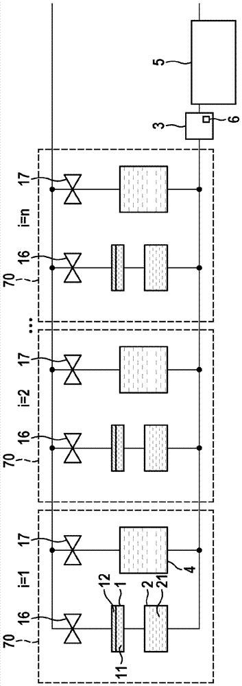
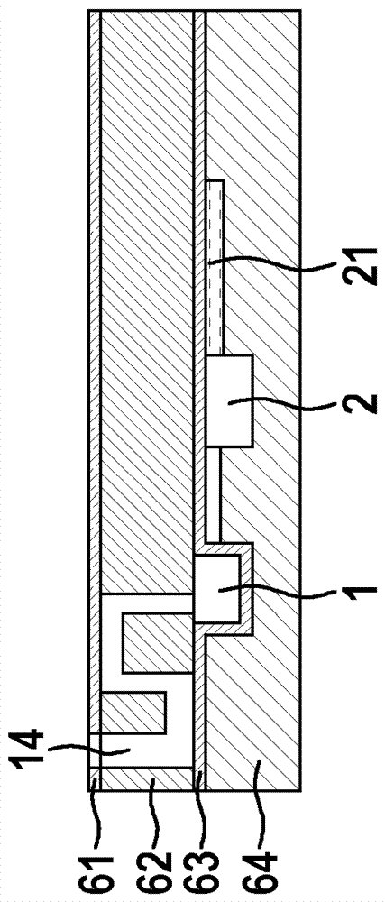
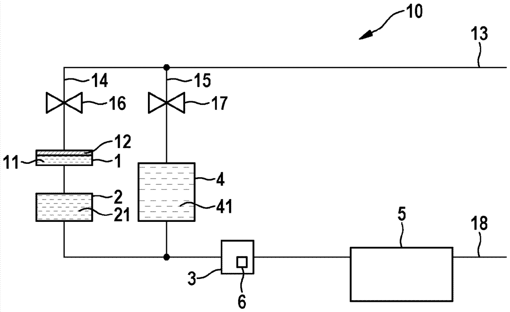
[0023] figure 1 The embodiment of an example of a device according to the invention is shown. The device 10 has a first chamber 1 , a second chamber 2 and a third chamber 3 . The first fluid 11 is located in the first chamber 1 and the second fluid 21 is located in the second chamber 2 . The first fluid 11 is, for example, a gas or a gas mixture, the second fluid 21 is preferably a liquid, which can contain the sample constituents to be detected. The third chamber 3 can have detection elements 6 , in particular sensors for biological or chemical samples. The detection element can, for example, have an immobilized carrier, for example an antigen or an antibody, with probes immobilized thereon, wherein preferably the detection can take place optically, for example by measuring fluorescent radiation or electrically. The first chamber 1 is fluidly connected to the third chamber 3 through the second chamber 2 . The device according to the invention also has a membrane 12 which...


PUM


Abstract

A device (10, 60), in particular a microfluidic device for performing an immunoassay, having first, second and third fluidly connected chambers (1, 2, 3) and a membrane ( 12), characterized in that, in the case of a pre-set deflection of the diaphragm (12) towards the first chamber (1), the first fluid (11) is at least partially released from the first chamber (1) Introduced into the second chamber (2) in such a way that the second fluid (21) is at least partially displaced from the second chamber (2) into the third chamber (3) in such a way that the third chamber (3) is completely filled with the first Two fluids (21) are filled.

Description

Background technique [0001] Immunoassays constitute a standard method in bioanalysis for the identification of electrolytes formed from mostly liquid samples. These tests are usually based on the specific binding between the antibody and the antigen. Immunoassays are characterized by a repeating sequence of process steps. These steps in this regard generally comprise the addition of a liquid to the detection area, the interaction of the sample constituents present in the liquid with the detection element during a pre-set period of time and subsequently cleaning the detection area with a washing liquid. [0002] For applications in microfluidics, miniaturized devices, so-called "lab-on-a-chip" systems, are known which enable an at least partially automated procedure of these steps. However, for the operation of these systems, additional external pumps and externally connected valves are required. Contents of the invention [0003] Invention advantage [0004] The present ...

Claims


Application Information

Patent Timeline
Patent Type & Authority Patents(China)
IPC IPC(8): B01L3/00
CPCB01L3/50273B01L2300/0816B01L2300/0867B01L2300/087B01L2300/0887B01L2300/123B01L2400/0481B01L2400/0475
Inventor T.布雷特施奈德C.多雷尔
Owner ROBERT BOSCH GMBH
Why Eureka
Try Eureka