Motion strategies for scanning microscope imaging

An imaging and axis movement technology, applied in microscopes, instruments, optical components, etc., can solve problems such as image distortion, slow speed, and poor performance

Inactive Publication Date: 2016-06-15
3SCAN
View PDF10 Cites 2 Cited by
  • Summary
  • Abstract
  • Description
  • Claims
  • Application Information

AI Technical Summary

Problems solved by technology

These and other artifacts can result in distorted images, low resolution, poor performance, and slow speeds

Method used


Image

  • Motion strategies for scanning microscope imaging
  • Motion strategies for scanning microscope imaging
  • Motion strategies for scanning microscope imaging

Examples


Embodiment Construction

[0042] Example embodiments of the present disclosure and advantages thereof will now be best understood by referring to the drawings herein, in which like numerals refer to like parts.

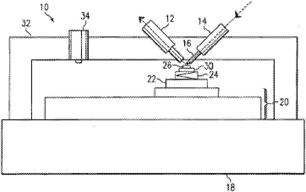
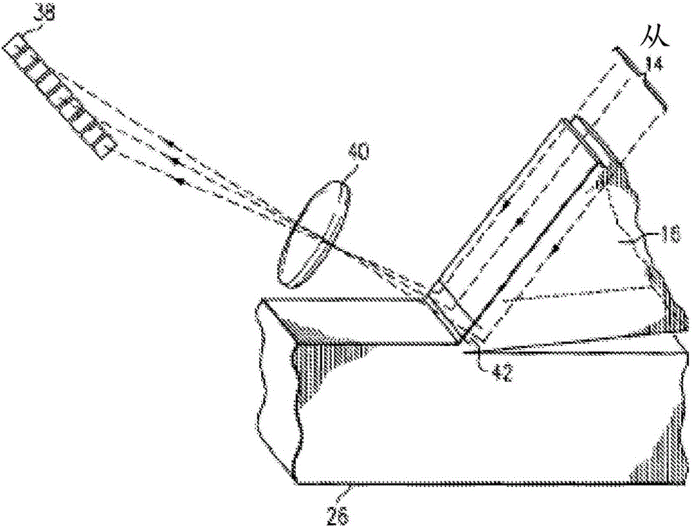
[0043] Embodiments described herein may provide several technical advantages. For example, backscatter effects associated with undesired data can be substantially reduced or effectively eliminated. By using a cutting instrument that acts as an optical collimator, imaging of only the portion of the specimen to be examined can be achieved. Thus, inadvertent imaging of areas beneath portions of the cutting instrument can be eliminated. This may allow specimens to be evaluated in greater detail with enhanced accuracy and power, and without backscatter from portions of the specimen below the cutting instrument.

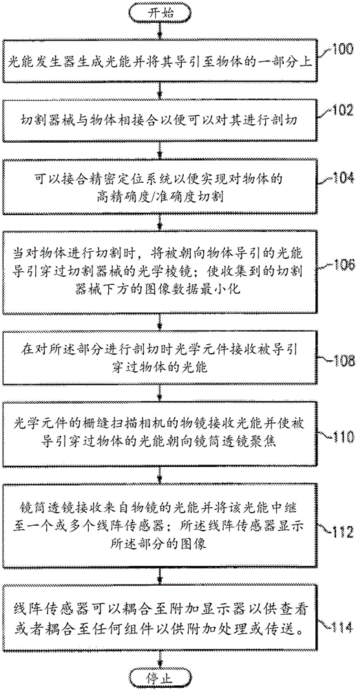
[0044] Since the imaging is performed while the section of the sample is cut with the cutting instrument, potential damage to the sample or degradation of the sample is substantially avoid...


PUM

PropertyMeasurementUnit
widthaaaaaaaaaa
thicknessaaaaaaaaaa

Abstract

Motion strategies in two and three dimensions for scanning microscope imaging are described. An object, sample, or specimen is mounted on a precision three- dimensional stage. The object is moved concurrently with respect to a first axis and a second axis orthogonal to the first against a cutting tool to cut the object. An image of the cut portion is generated as the object is moved. The cutting tool may act as an optical waveguide for illuminating the portion of the object cut. An optical element captures images of the cut and illuminated object. The object may further be concurrently moved with respect to a third axis orthogonal to both the first and second.

Description

[0001] cross reference [0002] This PCT application claims the benefit of US Provisional Application No. 61 / 897,913, filed October 31, 2013, which is hereby incorporated by reference. Background technique [0003] The present disclosure generally relates to systems and methods for imaging objects. In particular, the present disclosure relates to sectioning biological tissue and other material samples using a microtome, and more particularly, to microtome slicing trajectories. [0004] The field of microscopy has become increasingly important in today's society. One aspect of microscopy involves imaging the specimen or object to be evaluated. Imaging generally refers to the acquisition of data for the purpose of generating visualizations of a given area. Being able to efficiently and accurately image data about a given specimen can be important in determining one or more properties associated with that specimen or object. [0005] In many microscopy and imaging applicatio...

Claims


Application Information

Patent Timeline
Patent Type & Authority Applications(China)
IPC IPC(8): G01N1/06
CPCG01N1/06B26D5/007G02B21/32G01N1/286G01N21/55G02B21/002G02B21/362G01N2001/2873G01N2201/02G01N2201/06113
Inventor 马修·古德曼科迪·丹尼尔
Owner 3SCAN
Why Eureka
Try Eureka