
Automatic cutting machine with vision alignment function, and control method thereof

A visual alignment and cutting machine technology, which is applied in shoemaking machinery, clothing, metal processing, etc., can solve the problems of pattern outline damage, high labor cost, and low cutting efficiency

Active Publication Date: 2016-06-22
东莞市陆陆兴工业自动化科技有限公司
View PDF7 Cites 28 Cited by
  • Summary
  • Abstract
  • Description
  • Claims
  • Application Information

AI Technical Summary

Problems solved by technology

In the past, when cutting materials without patterns, it is only necessary to control the cutting die to automatically cut the materials at a certain distance and angle. Now, when cutting materials with printed patterns and outlines, the distance and angle of the pattern outlines are not necessarily uniform. Yes, and the cutting must be carried out according to the contour line, so it is necessary to accurately position the knife mold so that the knife mold and the outer contour of the material are completely matched before cutting. If the alignment is not accurate, the pattern outline on the fabric will be destroyed and become waste. cause waste
At present, the solution to this problem is to use a manual cutting machine to manually cut and accurately align the knife mold, which has low cutting efficiency and high labor costs.
[0004] In order to improve production efficiency, the use of this new type of multi-layer composite material will become more and more common in shoe-making and bag-making enterprises. Therefore, it is necessary to improve the automation level of cutting machines, reduce labor costs, improve cutting efficiency, and realize automatic and precise cutting of this new cutting piece. The material is particularly important, and the mechanical cutting machines currently on the market cannot solve this problem.

Method used

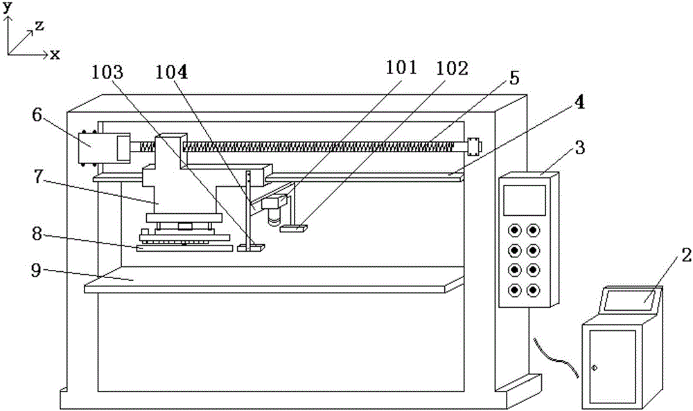
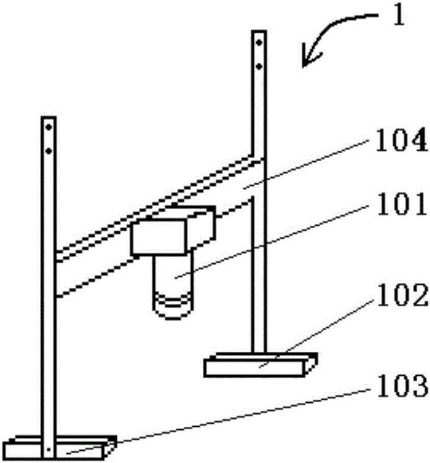

Image

  • Automatic cutting machine with vision alignment function, and control method thereof
  • Automatic cutting machine with vision alignment function, and control method thereof
  • Automatic cutting machine with vision alignment function, and control method thereof

Examples


Embodiment Construction

[0033] In the following, the application of the visual alignment automatic cutting machine of the present invention in the field of shoemaking will be further described in conjunction with the accompanying drawings.

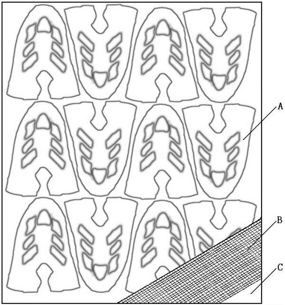
[0034] About the novel vamp material mentioned in the background technology such as figure 1 As shown, it is a new type of multi-layer composite belt outline pattern fabric. When cutting this material, it is required that the knife die will completely match the outer contour line printed on the surface layer A of the fabric pattern. Because the contours printed on the surface may be inconsistent in length, length and angle, it is impossible to cut by setting a fixed distance between die stepping and a fixed angle of die disc rotation, and each cutting requires precise alignment. This kind of material is not limited to the three layers shown in the figure, but may also be two or more layers, because the surface is printed with the commonality of the contour of the...


PUM


Abstract

The invention discloses an automatic cutting machine with a vision alignment function, and a control method thereof. A vision photographing assembly and an alignment calculation system are additionally designed on the basis of the main body frame and system of the existing cutting machine. Before each cutting action, the vision photographing assembly photographs a pre-cut fabric area, shoots a fabric outline position into a picture, and conveys the picture to the alignment calculation system; the alignment calculation system calculates the movement distances of the driven cutting die base and blanking table surface, and the rotation angle of a cutting die disc according to the deviation position of an outline in the picture relative to a reference point; and a PLC drives the cutting die base and the blanking table surface to displace, and drives the cutting die disc to rotate an angle according to the allowance transmitted by the alignment calculation system, so that a cutting die is accurately located above a fabric, and the cutting die is pressed to complete cutting. The system continuously repeats the steps of photographing, offset calculation, and alignment cutting, thus efficiently, accurately and fully automatically completing the cutting working for the fabric.

Description

technical field [0001] The invention relates to the technical field of cutting machines, in particular to a cutting machine for fabric cutting in industries such as shoemaking and leather goods processing. Background technique [0002] With the improvement of living standards, people have more and more diverse requirements for the shape and style of shoes, leather goods and other products, which means that the shapes of related fabrics that need to be cut are becoming more and more complex, and it is necessary to continuously improve the automation level of cutting machines , to save labor and material costs and improve processing efficiency. [0003] Shoemaking and bagmaking are generally made by stitching pieces of different shapes. The pieces of different shapes are obtained by cutting fabrics on cutting machines with forming knife molds. The fabrics that can be cut can be leather, cloth, plastic and other materials. . The cutting machine is a common equipment used for ...

Claims


Application Information

Patent Timeline
Patent Type & Authority Applications(China)
IPC IPC(8): B26F1/40B26D5/00B26D7/26B26D7/27A43D8/10
CPCA43D8/10B26D5/007B26D7/2628B26D7/27B26F1/405B26F2001/402
Inventor 詹新詹静
Owner 东莞市陆陆兴工业自动化科技有限公司
Learn More