
Long Fiber Overmolding

A cladding and mold technology, applied in the field of fiber composite material production equipment, can solve problems such as the impact of fiber reinforced composite material performance, and achieve the effect of performance improvement

Active Publication Date: 2018-05-08
NANJING GIANT MACHINERY
View PDF3 Cites 0 Cited by
  • Summary
  • Abstract
  • Description
  • Claims
  • Application Information

AI Technical Summary

Problems solved by technology

[0004] For fiber-reinforced composites produced by traditional processes, the properties of fiber-reinforced composites are affected to a certain extent due to the shearing and crushing of fibers in the twin-screw extruder

Method used


Image

  • Long Fiber Overmolding
  • Long Fiber Overmolding
  • Long Fiber Overmolding

Examples


Embodiment Construction

[0038] The present invention will be further explained below in conjunction with the accompanying drawings.

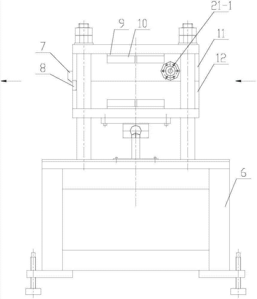
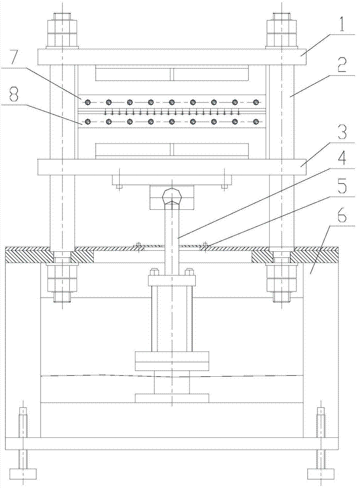
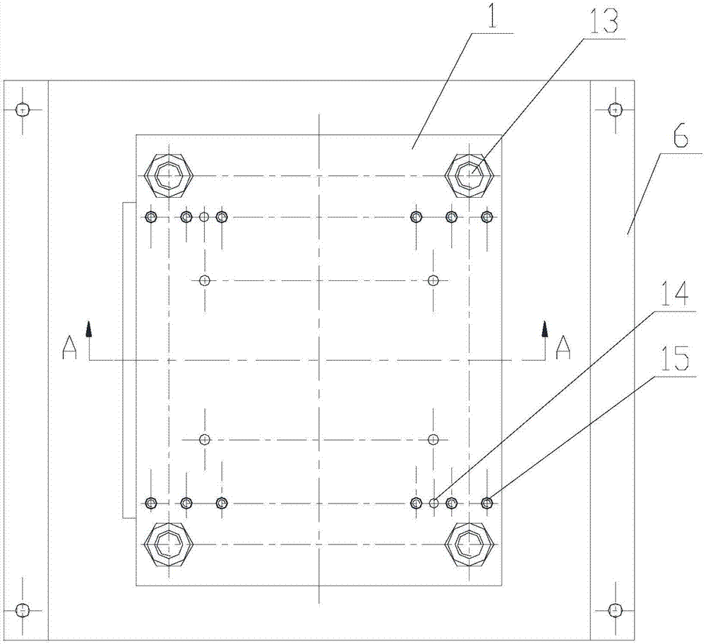
[0039] Such as Figure 1-15 As shown, a long fiber coating mold of the present invention includes an upper platen 1, a sliding column 2, a lower plate 3, a hydraulic device 4, a base composition 6, a die baffle plate 7, a die 8, a heat shield 9, An electric heater 10, an upper template composition 11 and a lower template composition 12.

[0040] The lower end of the strut 2 is fixedly installed on the upper part of the base composition 6 by the hexagonal nut 13, the upper platen 1 is fixedly mounted on the top of the strut 2 by the hexagonal nut 13, the hydraulic cylinder of the hydraulic device 4 is installed inside the base composition 6, and the hydraulic device The piston rod of 4 stretches out from the upper opening of the base composition 6, the sliding plate 3 is enclosed within on the sliding column 2, and the bottom of the sliding plate 3 is installed on the ...


PUM


Abstract

The invention discloses a filament coating mold which comprises an upper pressing plate and a lower sliding plate. The upper pressing plate is installed at the top end of a sliding column, the sliding column is sleeved with the lower sliding plate, the bottom of the lower sliding plate is installed at the top end of a piston rod of a hydraulic device, an upper mold plate assembly is installed on the upper pressing plate, a lower mold plate assembly is installed on the lower sliding plate, electric heaters are installed on an upper mold plate body of the upper mold plate assembly and a lower mold plate body of the lower mold plate assembly, an upper corrugated strip is installed on the bottom face of the upper mold plate body, a mouth mold is installed on the front end face of the lower mold plate body, a lower corrugated strip A, a lower corrugated strip B and a lower corrugated strip C are installed on the top face of the lower mold plate body, mold closing and opening of the lower mold plate body and the upper mold plate body are achieved under the drive of the hydraulic device, a melt cavity is formed between the lower mold plate body and the upper mold plate body, and each corrugated strip forms a corrugated flow pass inside the melt cavity. According to the filament coating mold, continuous fiber can be completely coated with a polymer melt, the phenomenon that fiber is sheared and broken when added into a double-screw extruder is avoided, and the fiber-enhanced composite material performance is greatly improved.

Description

technical field [0001] The invention relates to fiber composite material production equipment, in particular to a long fiber covering mold. Background technique [0002] Reinforcement modification is a method of adding reinforcing materials to the polymer matrix to improve the properties of the polymer. Commonly used reinforcing fibers are mainly organic fibers and inorganic fibers. Organic fibers mainly include carbon fibers, etc., and inorganic fibers mainly include glass fibers. Wait. Since the polymer matrix components of the continuous phase and the fibers of the dispersed phase can "supplement from each other" and "synergize" in the composite material, the material combines the properties of each component, thereby greatly expanding the use of polymer materials. In polymer composites, reinforcing fibers are mainly used to increase the strength, modulus and hardness of the polymer. [0003] At present, co-rotating parallel twin-screw extruders are generally used to me...

Claims


Application Information

Patent Timeline
Patent Type & Authority Patents(China)
IPC IPC(8): B29C41/38B29C41/30B29C41/46B29B15/14B29B9/06
CPCB29B9/06B29B15/14B29C41/30B29C41/38B29C41/46
Inventor 霍庆宪陈广义张照奇王大勇
Owner NANJING GIANT MACHINERY
Learn More