Arable pitch mounting for aircraft gas turbine engine

A technology for aviation gas turbines and aeroengines, applied in the direction of gas turbine power units, arrangement/installation of power units, jet power units, etc., capable of solving problems such as high fuel consumption and/or weight

Active Publication Date: 2016-06-22
GENERAL ELECTRIC CO
View PDF10 Cites 7 Cited by
  • Summary
  • Abstract
  • Description
  • Claims
  • Application Information

AI Technical Summary

Problems solved by technology

This results in higher fuel consumption and / or weight

Method used


Image

  • Arable pitch mounting for aircraft gas turbine engine
  • Arable pitch mounting for aircraft gas turbine engine
  • Arable pitch mounting for aircraft gas turbine engine

Examples


Embodiment Construction

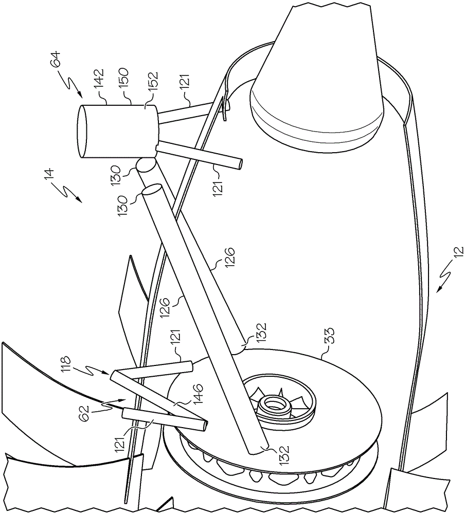
[0059] Embodiments described herein are described in connection with ducted fans and open rotor aviation gas turbine engines. Examples include ductless reverse rotatable front fan high bypass ratio engines, or UDFs.

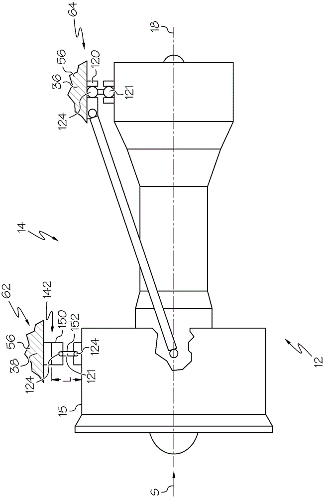
[0060] exist figure 1 An exemplary aviation gas turbine engine 12 is shown in , and more particularly, a ductless reverse rotatable front fan high bypass ratio gas turbine engine 12 , also referred to herein as an open rotor gas turbine engine, is shown. Ductless and open rotor engines have open fan tips 13 that are not wrapped or surrounded radially outward by any fan casing or nacelle. Engine 12 is defined about engine centerline axis 18 and is suitably designed to be mounted by brackets 56 to a wing or fuselage (not shown) of an aircraft. The engine 12 extends rearward or downward from a front or upstream end 20 and a rear or downstream end 22 of the engine 12 . The engine 12 includes an outer casing 24 coaxially arranged about the centerline axis 18 . The...


PUM


Abstract

The light source control apparatus controls drive of multiple light sources included in a light source unit to be used in a state where the multiple light sources are lit. The multiple light sources each include multiple light-emitting elements. The light source control apparatus includes an acquirer acquiring temporal information relating to a temporal change of each of the light sources, an estimator acquiring an estimated lifetime of each of the multiple light sources by using the temporal information, and a controller decreasing, when the multiple light sources include a first light source whose estimated lifetime is shorter than a target lifetime set for the light source unit, a light emission amount of the first light source.

Description

technical field [0001] The present invention generally relates to the installation of aero-engines to aircraft. Background technique [0002] Aeroengines (eg, gas turbine engines) may be mounted to aircraft at various locations (eg, wings, fuselage, or tail). Aviation engines include gas turbine driven engines, electric engines, hybrid engines, and piston engines. The engines are typically mounted to the aircraft at axially separated forward and rearward or forward and rearward locations by corresponding forward and rearward or forward and rearward mounts. Loads typically include vertical loads, such as the weight of the engine itself, axial thrust loads generated by the engine, lateral loads (such as those caused by wind turbulence), and rolling loads or moments caused by the rotational operation of the engine . The mount accommodates both axial and radial thermal expansion and contraction of the engine relative to the support bracket. [0003] U.S. Patent No. 5,320,307...

Claims


Application Information

Patent Timeline
Patent Type & Authority Applications(China)
IPC IPC(8): B64D27/26B64D27/10
CPCB64D27/26B64C19/00B64D27/10B64D27/16B64D2027/005B64D2027/266B64D2027/262
Inventor I.F.普伦蒂斯
Owner GENERAL ELECTRIC CO
Why Eureka
Try Eureka