
Contact type deformation heat box for elasticizer

A deformation heat box and contact technology, applied in textiles and papermaking, etc., can solve the problems of poor thermal insulation effect, high heat loss rate, and high thermal conductivity of thermal insulation materials, so as to improve thermal insulation effect, reduce thermal conductivity, and save energy effect of effect

Active Publication Date: 2016-06-22
戚其杰
View PDF6 Cites 12 Cited by
  • Summary
  • Abstract
  • Description
  • Claims
  • Application Information

AI Technical Summary

Problems solved by technology

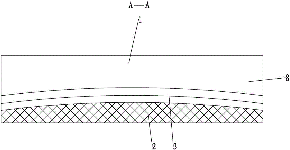
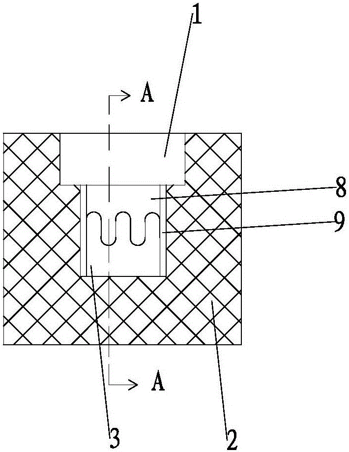
In the structure of the existing contact deformation heat box ( figure 1 , figure 2 As shown), the hot box is obliquely installed on the upper part of the texturing machine. When the flat hot 1 is closed, there is a large gap 8 between the hot 1 and the arc-shaped hot rail 3. The four hot surfaces of the gap 8 are exposed to the flowing In the air, the obliquely installed heat box main body 2 will cause the gap 8 to form a chimney effect, forming a large convection, and the heat loss rate is high; at the same time, there is no thermal insulation material in the hot box 1, and the thermal insulation material filled in the thermal box main body 2 has a good thermal insulation effect Poor, high thermal conductivity, huge energy consumption

Method used


Image

  • Contact type deformation heat box for elasticizer
  • Contact type deformation heat box for elasticizer
  • Contact type deformation heat box for elasticizer

Examples


Embodiment Construction

[0018] Below the present invention will be further described in conjunction with the embodiment in the accompanying drawing:

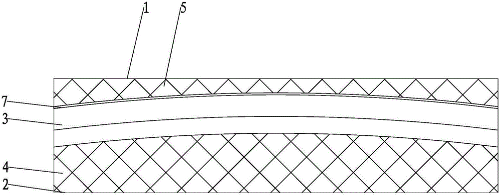
[0019] like Figure 3~6 As shown, the present invention mainly comprises hot box 1, hot box main body 2 and hot rail 3, and the middle part of hot box main body 2 is provided with hot rail installation chamber 6, and arc-shaped hot rail 3 is set in the hot rail installation chamber 6.

[0020] The upper end surface of the heating box main body 2 coincides with the upper end surface of the heating rail 3, so that the upper end surface of the heating box main body 2 is close to the upper end surface of the heating rail 3, and a certain space is left between the upper end surface of the heating box main body 2 and the convex surface of the heating rail 3. The gap 7, the range of the gap 7 is 0~10mm.

[0021] A heat insulation layer 4 is provided between the outer wall of the heat box main body 2 and the heat rail 3, and the heat insulation layer 4 is fil...


PUM


Abstract

The invention relates to a deformation heat box, in particular to a contact type deformation heat box for an elasticizer, and belongs to the technical field of elasticizers. The deformation heat box comprises a heat door, a heat box body and a heat rail, wherein the upper end face of the heat box body is matched with the upper end face of the heat rail, and a certain gap is reserved between the upper end face of the heat box body and a bulged face of the heat rail; the heat door is arranged at the upper end of the heat rail, and is rotationally connected to the heat box body; one end face, towards the heat box body, of the heat door is matched with the upper end face of the heat box body, so that the surface of the heat door is closely attached to the upper end face of the heat box body. According to the deformation heat box, the heat door lower surface and the heat box body lower surface both matched with the heat rail surface are adopted, so that the heat rail is enabled to be closely attached to the heat door lower surface and the heat box body lower surface; meanwhile, the heat door and the heat box body are filled with composite heat-insulation felt inside, so that the heat insulation effect is improved, the heat conductivity is effectively reduced, and a relatively good energy-saving effect is achieved.

Description

technical field [0001] The invention relates to a deformation heating box, in particular to a texturing machine contact type deformation heating box, which belongs to the technical field of texturing machines. Background technique [0002] Texturing machine is a kind of textile machine that can process polyester, nylon and other untwisted yarns into elastic yarns with medium-strength and low elastic properties through false twist deformation. During the texturing process, one step takes place in a texturing oven. In the structure of the existing contact deformation heat box ( figure 1 , figure 2 As shown), the hot box is obliquely installed on the upper part of the texturing machine. When the flat hot 1 is closed, there is a large gap 8 between the hot 1 and the arc-shaped hot rail 3. The four hot surfaces of the gap 8 are exposed to the flowing In the air, the obliquely installed heat box main body 2 will cause the gap 8 to form a chimney effect, forming a large convect...

Claims


Application Information

Patent Timeline
Patent Type & Authority Applications(China)
IPC IPC(8): D02G1/02
CPCD02J13/003D02G1/0206
Inventor 戚其杰
Owner 戚其杰
Learn More