
Foundation pit supporting method capable of automatically controlling horizontal displacement of underground diaphragm wall

An underground diaphragm wall and foundation pit support technology, applied in excavation, infrastructure engineering, construction, etc., can solve the problem of inability to achieve dynamic adjustment, reduce the risk of foundation pit deformation, reduce horizontal displacement, and the system is simple reliable results

Active Publication Date: 2016-06-22
CHINA RAILWAY 16 BUREAU GRP BEIJING METRO ENG CONSTR +2
View PDF7 Cites 2 Cited by
  • Summary
  • Abstract
  • Description
  • Claims
  • Application Information

AI Technical Summary

Problems solved by technology

However, the adjustment basis of computer control in this patent still needs to be manually collected, and it has not really realized automatic support axial force compensation according to changes in construction conditions.
Moreover, the difference in groundwater levels on both sides of the underground diaphragm wall caused by diving pre-precipitation is a dynamic process, so the horizontal displacement of the underground diaphragm wall caused by the difference in groundwater level is also a dynamic process, and real-time dynamic adjustment cannot be achieved through manual collection.
Therefore, the method proposed in the above patent still has room for further improvement in the degree of automation and control accuracy of support force compensation

Method used


Image

  • Foundation pit supporting method capable of automatically controlling horizontal displacement of underground diaphragm wall
  • Foundation pit supporting method capable of automatically controlling horizontal displacement of underground diaphragm wall
  • Foundation pit supporting method capable of automatically controlling horizontal displacement of underground diaphragm wall

Examples


Embodiment

[0039] A foundation pit is located in a soft soil area, and the groundwater level is 0.000m. The size of the foundation pit is 50m×10m, and the elevation of the bottom of the foundation pit is -5m. The foundation pit enclosure adopts an underground diaphragm wall, the thickness of which is 0.5m, and the stiffness of the diaphragm wall per unit length is 120000kN m 2 , the elevations of the top and bottom of the underground diaphragm wall are 0.000m and -8.0m, respectively. Before the foundation pit is excavated, the well point dewatering method is used to carry out pre-dewatering in the foundation pit.

[0040] Step 1: Determined by the size of the foundation pit, it is necessary to arrange a set of horizontal supports every 5m along the length of the foundation pit, a total of 9 sets;

[0041] At the midpoint of each group of horizontal supports, a lattice column with a section size of 400mm×400mm welded by four 100mm×100mm×7mm angle steels and several 400mm×70mm×7mm strips...


PUM

PropertyMeasurementUnit
Outer diameteraaaaaaaaaa
Thicknessaaaaaaaaaa

Abstract

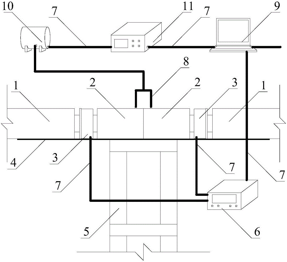
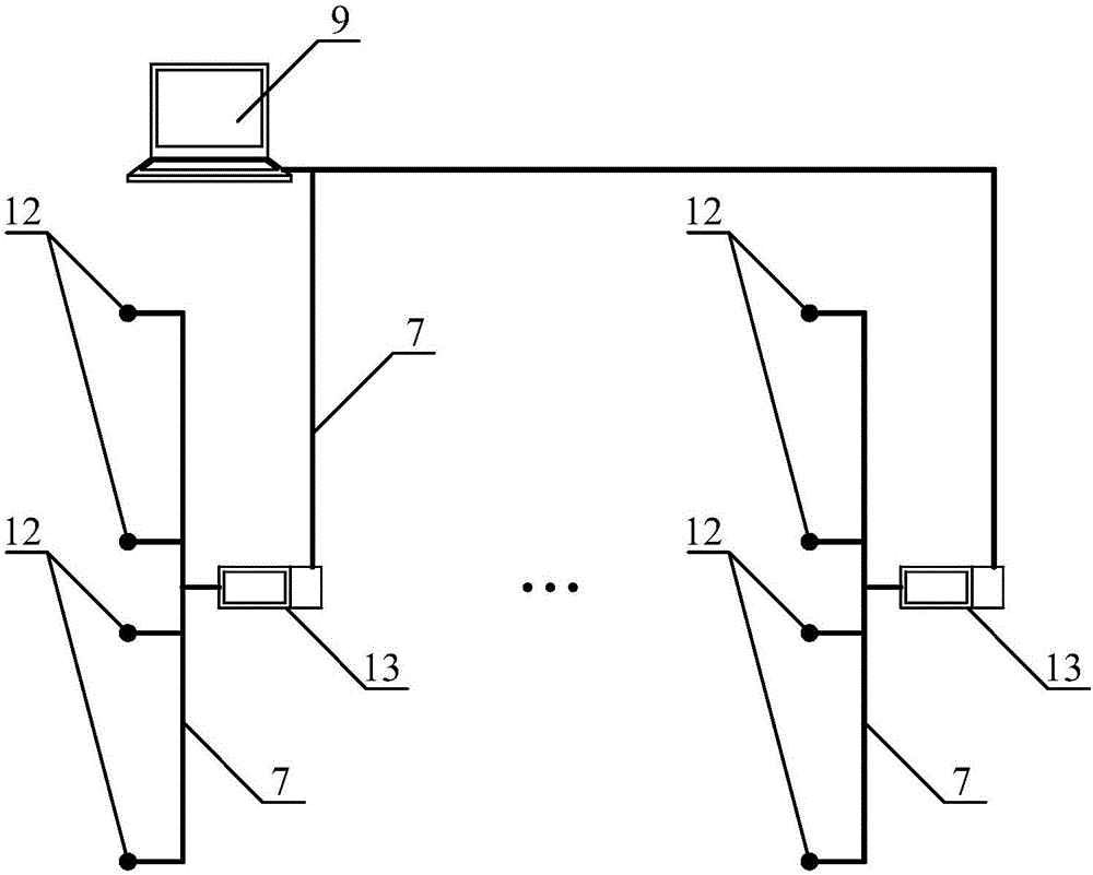
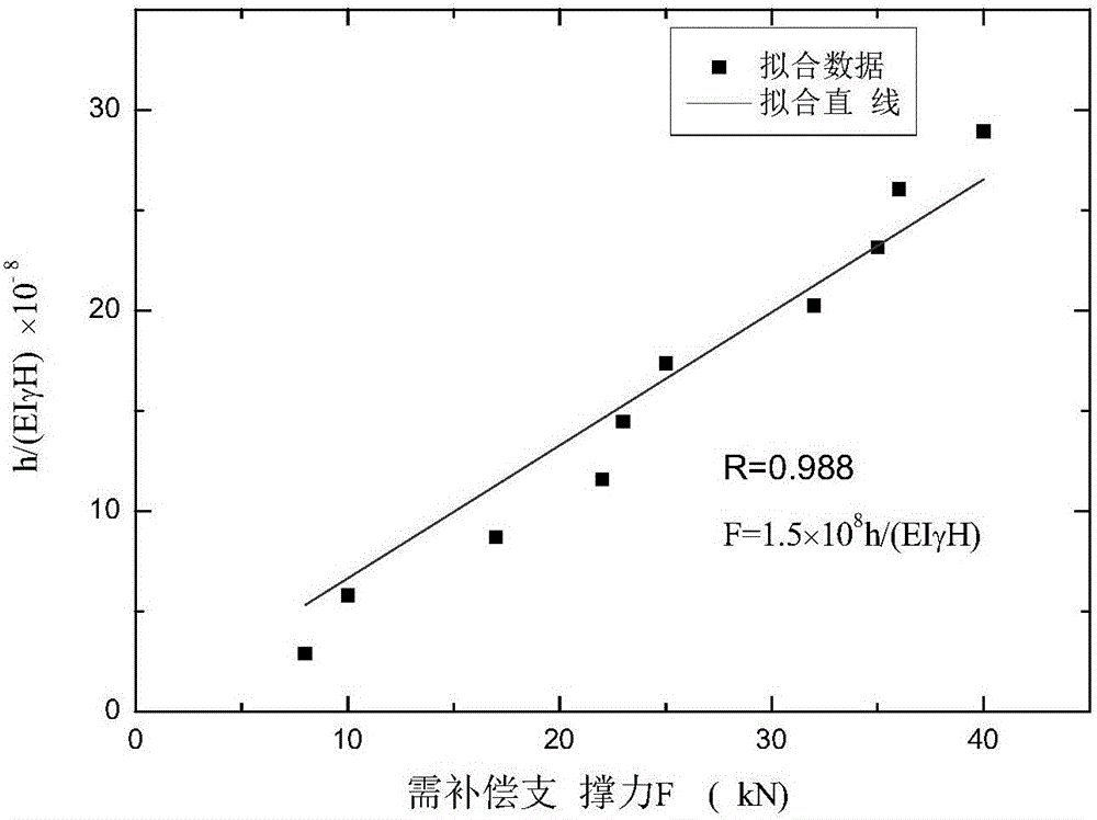
The invention provides a foundation pit supporting method capable of automatically controlling horizontal displacement of an underground diaphragm wall. According to the method, a set of horizontal supports are arranged in the length direction of a foundation pit, and hydraulic jacks are arranged in the horizontal supports; each set of horizontal support is provided with an underground water level gauge, a water level monitor, a front controller and a pressure monitor; the water level monitor is used for recording the underground water level depths in real time, wherein the underground water level depths are measured by the underground water level gauge in real time, the difference value of the underground water level depths on the two sides of the underground diaphragm wall is determined, and the difference value of the underground water level depths is uploaded to a central control device automatically; and numerical simulation is conducted according to the project conditions of the foundation pit, the supporting force value which is generated by the underground water level change and needs compensation is determined, the underground water level change is monitored automatically through the underground water level gauges, supporting force compensation is conducted on the horizontal supports automatically through the hydraulic jacks, and accordingly the horizontal displacement, caused by phreatic water and rainwater in the foundation pit, of the underground diaphragm wall is reduced.

Description

technical field [0001] The invention relates to a technical method in the technical field of construction engineering, in particular to a foundation pit support method for automatically controlling hydraulic jacks according to changes in groundwater levels to reduce the horizontal displacement of underground diaphragm walls. Background technique [0002] There are more and more construction projects that need to excavate foundation pits in my country's coastal soft soil areas. Since the groundwater level in coastal areas is generally high, it is generally necessary to carry out diving pre-precipitation in the foundation pit when excavating the foundation pit. At present, the most commonly used foundation pit dewatering method is the well point dewatering method: before the foundation pit is excavated, a certain number of filter pipes (wells) are buried around the foundation pit in advance, and water is pumped with pumping equipment to reduce the groundwater level in the foun...

Claims


Application Information

Patent Timeline
IPC IPC(8): E02D17/04
Inventor 朱小藻蔡连利高宪民周阳宗崔松涛刘锐沈水龙任栋杰吴怀娜范志高唐德刚余大成张益柱余贵良陶红杰黄帮兴闫江涛
Owner CHINA RAILWAY 16 BUREAU GRP BEIJING METRO ENG CONSTR
Learn More