Piston body oil chamber sealing device

A sealing device and plug body technology, which is applied to the sealing device of the engine, piston, liquid variable capacity machinery, etc., can solve the problem that the piston and cylinder cannot be completely sealed, and achieve the purpose of reducing temperature, preventing leakage and realizing efficient utilization. Effect

Inactive Publication Date: 2016-06-22
甘勇
View PDF7 Cites 0 Cited by
  • Summary
  • Abstract
  • Description
  • Claims
  • Application Information

AI Technical Summary

Problems solved by technology

Without changing the existing research ideas, the goal of completely sealing the piston and cylinder will never be achieved

Method used


Image

  • Piston body oil chamber sealing device
  • Piston body oil chamber sealing device
  • Piston body oil chamber sealing device

Examples


Embodiment 1

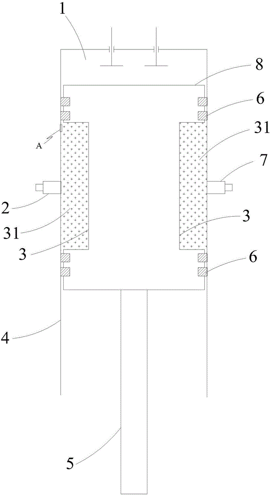
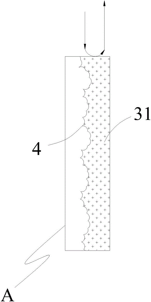
[0036] Such as figure 2 and image 3 As shown, the plug body oil cavity sealing device of this embodiment includes a cylinder 4 and a plug body 8 located in the cylinder 4 and matched with the cylinder 4 , the connection between the plug body 8 and the side wall of the cylinder 4 An annular sealing oil groove 3 is provided between them, and the annular sealing oil groove 3 is provided on the side wall of the plug body 8 . The annular sealing oil groove 3 is filled with sealing oil 31 . Two piston rings 6 are respectively arranged on the upper and lower sides of the annular sealing oil groove 3 , and the piston rings 6 are located between the plug body 8 and the side wall of the cylinder 4 . The side wall of the cylinder 4 is provided with an oil inlet 2 and an oil outlet 7 that are opposite and communicated with the annular seal oil groove 3, and the oil inlet 2 and the oil outlet 7 are respectively located in the ring seal. The middle of oil tank 3.

[0037] The lower en...

Embodiment 2

[0040] Such as Figure 4 As shown, the plug body oil cavity sealing device of this embodiment includes a cylinder 4 and a plug body 8 located in the cylinder 4 and matched with the cylinder 4 , the connection between the plug body 8 and the side wall of the cylinder 4 Two annular sealing oil grooves 3 are arranged between them, and the two annular sealing oil grooves 3 are sequentially opened on the side wall of the plug body 8 from top to bottom. The annular sealing oil groove 3 is filled with sealing oil 31 . Two piston rings 6 are respectively arranged on the upper and lower sides of each annular sealing oil groove 3 , and the piston rings 6 are located between the plug body 8 and the side wall of the cylinder 4 . The side wall of the cylinder 4 is provided with an oil inlet 2 and an oil outlet 7 that are opposite and communicated with the annular seal oil groove 3, and the oil inlet 2 and the oil outlet 7 are respectively located in the ring seal. The middle of oil tank ...

Embodiment 3

[0045] Such as Figure 5 As shown, the plug body oil cavity sealing device of this embodiment is used in a natural gas compressor, and includes a sealing sleeve 4 and a moving shaft 9 located in the sealing sleeve 4 and cooperating with the sealing sleeve 4. The moving shaft Two annular sealing oil grooves 3 are arranged between 9 and the side wall of the sealing sleeve 4 , and the two annular sealing oil grooves 3 are sequentially provided on the side wall of the moving shaft 9 from top to bottom. The annular sealing oil groove 3 is filled with sealing oil 31 . Two piston rings 6 are respectively arranged on the upper and lower sides of each annular sealing oil groove 3 , and the piston rings 6 are located between the moving shaft 9 and the side wall of the sealing sleeve 4 . The side wall of the sealing sleeve 4 is provided with an oil inlet 2 and an oil outlet 7 opposite to the annular sealing oil groove 3, and the oil inlet 2 and the oil outlet 7 are respectively located ...


PUM


Abstract

The invention belongs to the technical field of piston seal, and particularly provides a piston body oil chamber sealing device which comprises an air cylinder (4) and a piston body (8) positioned in the air cylinder (4) and matched with the air cylinder (4); a circular sealing oil groove (3) is formed between the piston body (8) and the side wall of the air cylinder (4) and filled with sealing oil (31). The piston body oil chamber sealing device, provided by the invention, has the benefits as follows: a thorough sealing effect is achieved, air leakage is completely avoided, meanwhile, wear reduction, wear resistance and temperature reduction are achieved, the service life of the equipment is prolonged, and high efficient utilization of resource is realized; besides, the piston mechanism has the advantages of high efficiency, high reliability and high stability, the oil consumption of an internal combustion engine is reduced, large-scale energy conservation and emission reduction is facilitated, and the production and usage cost is reduced.

Description

technical field [0001] The invention belongs to the technical field of piston sealing, and in particular relates to a sealing device for an oil chamber of a plug body. Background technique [0002] The piston is a mechanical part that reciprocates in the cylinder. The relative movement between the piston and the cylinder is used in many existing fields, such as the cylinder piston in the combustion chamber of a motor vehicle engine, and the living rod for compressing natural gas in a natural gas compressor. And the cylinder body, for example, the piston and the cylinder body that cooperate with each other to evacuate in the vacuum pump, and the like. Due to the ever-present reciprocating frictional motion, friction losses are high, and there is often a gap between the piston and the cylinder, which can lead to unintentional escape. In the field of motor vehicles, the cylinder piston is not tightly sealed, which is manifested in the exhaustion of fuel and gas motor vehicles ...

Claims


Application Information

Patent Timeline
Patent Type & Authority Applications(China)
IPC IPC(8): F02F3/00F02F11/00F04B39/00F04B39/04
CPCF02F11/00F02F3/00F04B39/0005F04B39/042
Inventor 唐国锐甘勇张翅
Owner 甘勇
Why Eureka
Try Eureka