Combustion chamber structure of circulating fluidized bed boiler

A circulating fluidized bed and furnace structure technology, applied in the field of super boilers, can solve the problems of difficulty in popularization, difficulty in inspection and maintenance of the inner ring heating surface, etc.

Active Publication Date: 2016-06-22
DONGFANG BOILER GROUP OF DONGFANG ELECTRIC CORP
View PDF9 Cites 2 Cited by
  • Summary
  • Abstract
  • Description
  • Claims
  • Application Information

AI Technical Summary

Problems solved by technology

[0004] However, due to steel frame layout, maintenance space and other reasons, the above-mentioned technology has certain requirements on the size of the inner ring, and can only be applied to boilers with a capacity of 660MW and above. In addition, the inner ring is a relatively closed space, and there are certain risks in running inspections. , there are also certain difficulties in the inspection and maintenance of the inner ring heating surface, so it is difficult to promote it in actual engineering

Method used


Image

  • Combustion chamber structure of circulating fluidized bed boiler
  • Combustion chamber structure of circulating fluidized bed boiler
  • Combustion chamber structure of circulating fluidized bed boiler

Examples


Embodiment 1

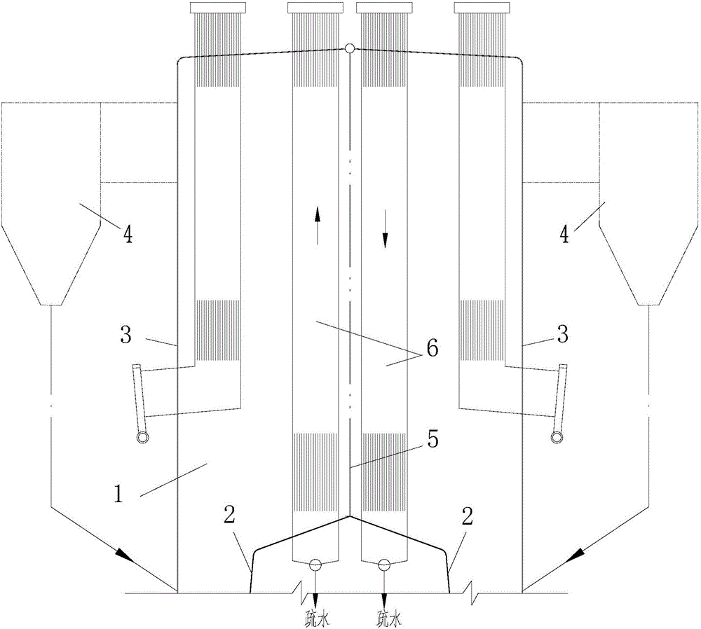
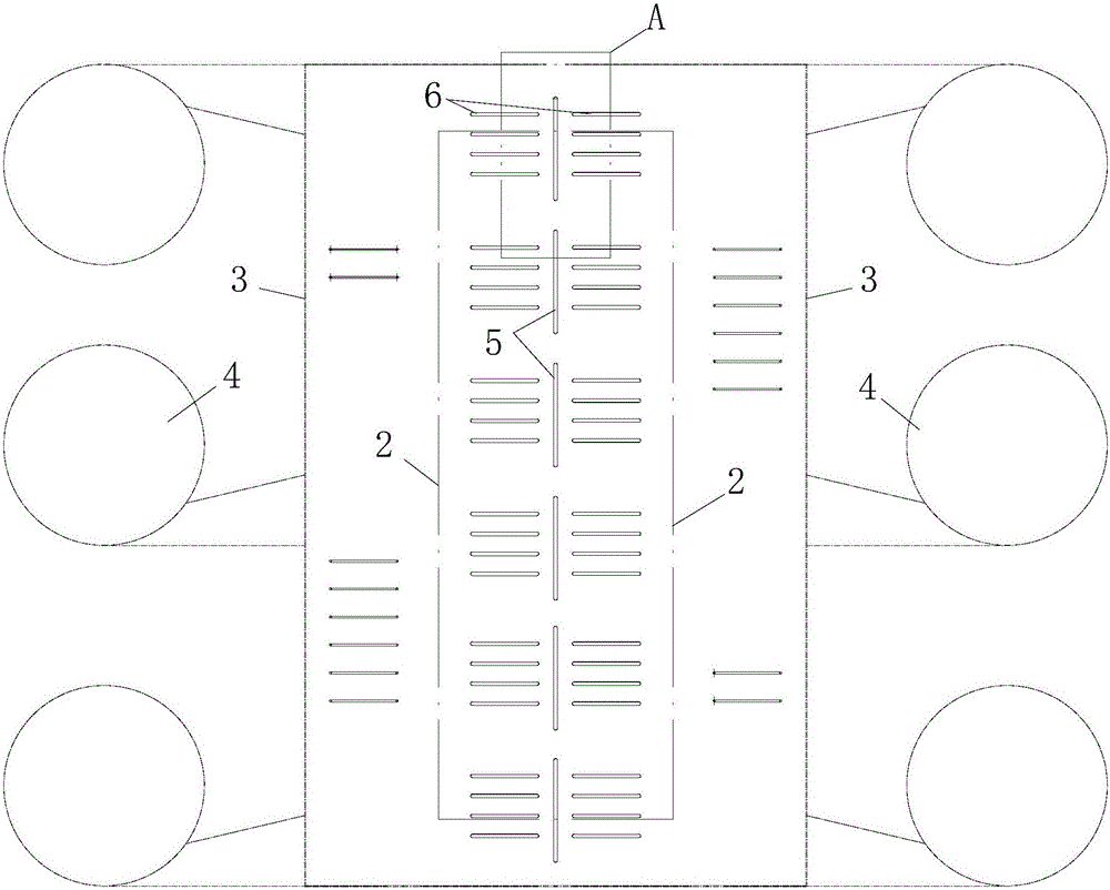
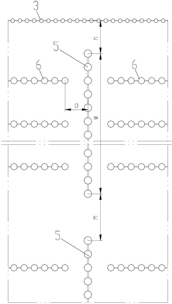
[0033] Such as Figure 1-4 as shown, Furnace structure of a circulating fluidized bed boiler , the air distribution plate and the lower furnace are annular structures, the inner ring and outer ring of the furnace 1 are polygonal, and the number of outer ring edges and inner ring edges is not less than 4, as shown in this embodiment, the inner ring and outer ring are rectangular. The inner ring water cooling wall 2 tubes and the outer ring water cooling wall 3 tubes in the lower part of the furnace 1 are not connected, the inner ring water cooling wall 2 tubes are inclined upward and inward, and the position of the boiler centerline at the junction of the dense phase area and the dilute phase area of ​​the furnace 1 is merged into A number of double-sided heated water-cooled tube panels 5, that is, each water-cooled tube panel is located in the same plane, and the water-cooled tube panel extends vertically upwards from the furnace ceiling to pass through the furnace 1, and ...

Embodiment 2

[0035] Such as Figure 5 As shown, this embodiment is basically the same as Embodiment 1, and the difference is that: the inner ring water-cooled wall intermediate header 7 corresponding to the double-sided heated water-cooled tube panel 5 is not provided, and the two inner ring water-cooled walls on both sides of the boiler centerline 2 The tubes are merged into a double-sided heated water-cooled tube-panel tube through the Y-shaped tube 8, which solves the problem of a certain lack of enthalpy in the inlet of the tube-panel required by the once-through boiler.

Embodiment 3

[0037] Such as Figure 6-9 As shown, this embodiment is basically the same as Embodiment 1, and the difference is that the inner ring water-cooled wall intermediate header 7 corresponding to the double-sided heated water-cooled tube panel 5 is not provided, and two or more inner headers on the same side of the boiler center line The ring water wall tube passes through the goblet tube 9 ( Figure 6 、 7 ) or rake tube 10 ( Figure 8 、 9 ) into a double-sided heated water-cooled tube-panel tube, which solves the problem of a certain lack of enthalpy in the inlet of the tube-panel required by the once-through boiler.


PUM


Abstract

The invention discloses a combustion chamber structure of a circulating fluidized bed boiler. An air distribution plate and a combustion chamber on the lower portion of the structure are both of an annular structure. Pipes of inner ring water cooling walls of the combustion chamber are inclined upwards and inwards and combined into multiple water cooling pipe panels of which double sides are heated in the boiler center line position at a junction of a dense-phase zone and a lean-phase zone of the combustion chamber, the water cooling pipe panels extend vertically and upwards and penetrate through the combustion chamber from a ceiling of the combustion chamber, and all water cooling pipe panels of which the double sides are heated are discontinuously arranged on the boiler center line. Multiple groups of superheated steam pipe panels of which the double sides are heated are further disposed on the two sides of each water cooling pipe panel of which the double sides are heated. The superheated steam pipe panels are perpendicular to the water cooling pipe panels of which the double sides are heated. The superheated steam pipe panels enter the combustion chamber from the lower portion of an inner ring of the annular combustion chamber and penetrate to outside from the top of the combustion chamber. The combustion chamber structure is applicable to the circulating fluidized bed boiler with the capacity level being lower than 660 MW or being 660 MW or above, so that the problems of limit of the annular combustion chamber on boiler capacity, arrangement of a heated surface in the boiler and the like are better solved, and the combustion chamber structure can adapt to schemes of circulating fluidized bed boilers of which the capacity levels are different.

Description

technical field [0001] The invention belongs to the field of circulating fluidized bed boilers, in particular to boilers with capacity levels less than 660MW. Background technique [0002] Up to now, more than 10 circulating fluidized bed boilers with supercritical parameters have been put into operation in the world, marking that circulating fluidized bed combustion technology has fully entered the supercritical era. In order to pursue higher power generation efficiency, especially in September 2014, the three ministries and commissions of the country jointly issued the "Coal Power Energy Conservation and Emission Reduction Upgrading and Transformation Action Plan". At the executive meeting of the State Council held in December 2015, it was decided to fully implement the The ultra-low emission and energy-saving transformation of power plants has greatly reduced the coal consumption and pollution emissions of power generation, and has stricter requirements on the coal consum...

Claims


Application Information

Patent Timeline
Patent Type & Authority Applications(China)
IPC IPC(8): F23C10/18
CPCF23C10/18F23C2206/10
Inventor 黄敏薛大勇巩李明聂立王鹏苏虎徐鹏胡修奎
Owner DONGFANG BOILER GROUP OF DONGFANG ELECTRIC CORP
Why Eureka
Try Eureka