A safety rope fracture strength detection fixture and testing machine
A technology for breaking strength and testing fixtures, which can be used in measuring devices, strength characteristics, and the strength of materials using stable tension/pressure testing. The effect of small weight and volume, uniform and reasonable force, and not easy to damage
- Summary
- Abstract
- Description
- Claims
- Application Information
AI Technical Summary
Problems solved by technology
Method used
Image
Examples
Embodiment 1
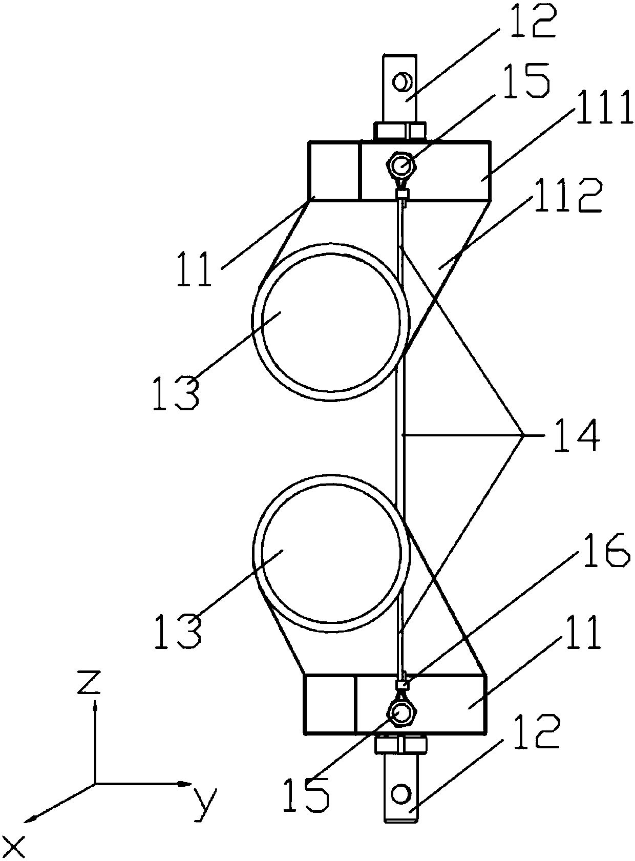
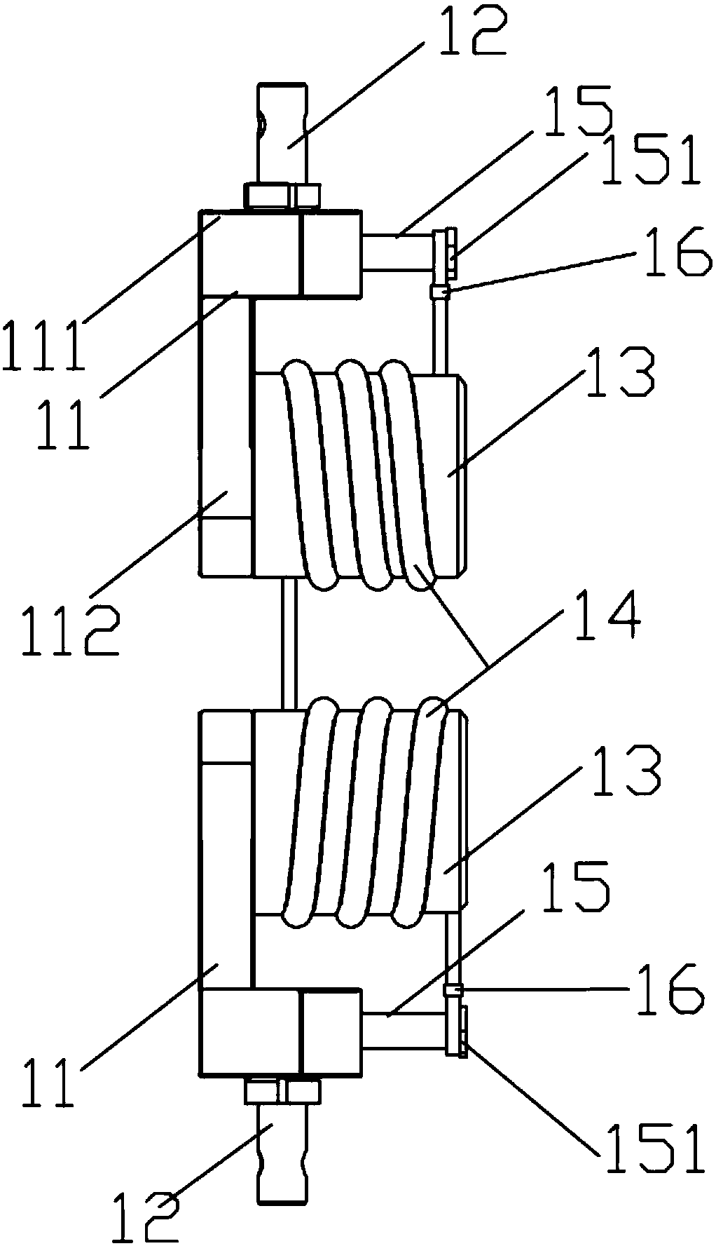
[0036] Such as figure 1 with 2 As shown, this embodiment provides a safety rope fracture strength detection fixture, including: a base 11, a winding wheel 13, a joint 12 and a pin 15, the base 11 includes a horizontal part 111 and a vertical part 112, and the vertical part 112 is vertical Fixed on one side of the bottom surface of the horizontal part 111; the winding wheel 13 is provided with a spiral winding groove, and one end of the winding wheel 13 is fixed on the vertical part 112 and is parallel to the horizontal part 111; the joint 12 is fixed on the top of the horizontal part 111 On the surface, the pin 15 is fixed on the side surface opposite to the vertical portion 112 on the horizontal portion 111, and is parallel to the horizontal portion 111, and one end of the test rope 14 is wound on the winding groove of the winding wheel 13, and its end is fixed on the winding groove of the winding wheel 13. On pin 15.
[0037]The clamp provided in this embodiment is suitabl...
Embodiment 2
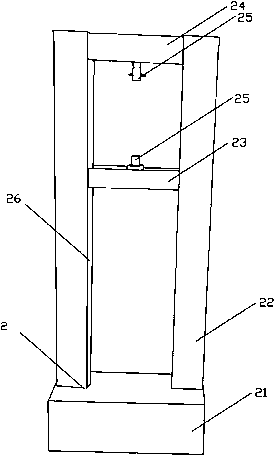
[0046] Such as image 3 As shown, this embodiment provides a safety rope fracture strength testing machine, including:
[0047] Frame 2, frame 2 comprises base 21, support rod 22, fixed crossbeam 24 and movable crossbeam 23, support rod 22 is two, is vertically fixed on the base 21 respectively, and the opposite side of two support rods 22 is provided with edge The guide rail 26 on the height direction of support bar 22, the two ends of movable beam 23 are respectively movably connected with the guide rails 26 of two support bars 22, and movable beam 23 can slide up and down along guide rail 26, and the two ends of fixed beam 24 are connected with two The top of the support rod 22 is fixed;
[0048] Two clamps, the clamps are as described in Example 1;
[0049] The two clamps are respectively connected with the fixed beam 24 and the movable beam 23 through the fixed structure 25;
[0050] It also includes a tension detection module, which is used to detect the maximum tensi...
PUM
 Abstract
Description
Claims
Application Information
 - R&D
- Intellectual Property
- Life Sciences
- Materials
- Tech Scout
- Unparalleled Data Quality
- Higher Quality Content
- 60% Fewer Hallucinations
Browse by: Latest US Patents, China's latest patents, Technical Efficacy Thesaurus, Application Domain, Technology Topic, Popular Technical Reports.
© 2025 PatSnap. All rights reserved.Legal|Privacy policy|Modern Slavery Act Transparency Statement|Sitemap|About US| Contact US: help@patsnap.com


