Identification method of fault indicator installation phase sequence

A fault indicator and identification method technology, applied in the direction of phase sequence/synchronous indication, etc., can solve problems such as installation errors, recording errors, and low efficiency, and achieve the effects of ensuring correctness, avoiding errors, and high efficiency

Inactive Publication Date: 2016-06-22
WILLFAR INFORMATION TECH CO LTD
View PDF6 Cites 13 Cited by
  • Summary
  • Abstract
  • Description
  • Claims
  • Application Information

AI Technical Summary

Problems solved by technology

The above-mentioned methods all have obvious disadvantages: because there are many installation points of the fault indicator, the installation site wiring is also relatively complicated, and the phase sequence is unclear. Man

Method used


Image

  • Identification method of fault indicator installation phase sequence
  • Identification method of fault indicator installation phase sequence
  • Identification method of fault indicator installation phase sequence

Examples


Embodiment Construction

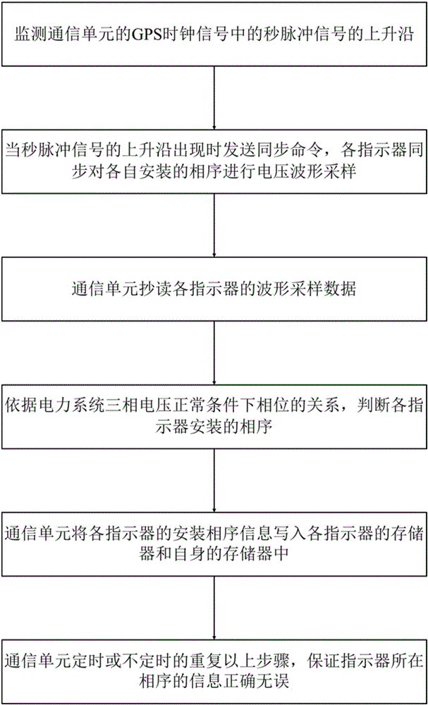
[0025] Such as figure 1 Shown is the flow chart of the method of the present invention: the method for identifying the installation phase sequence of the fault indicator provided by the present invention includes the following steps:

[0026] S1. Monitoring the rising edge of the second pulse signal in the GPS clock signal of the communication unit;

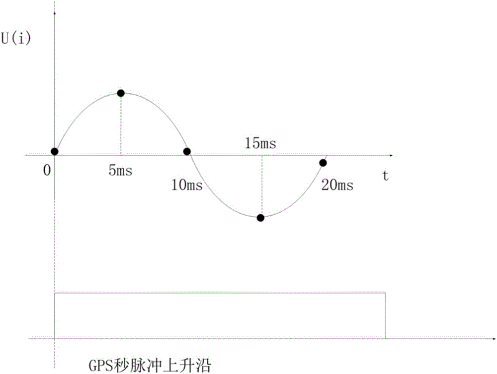
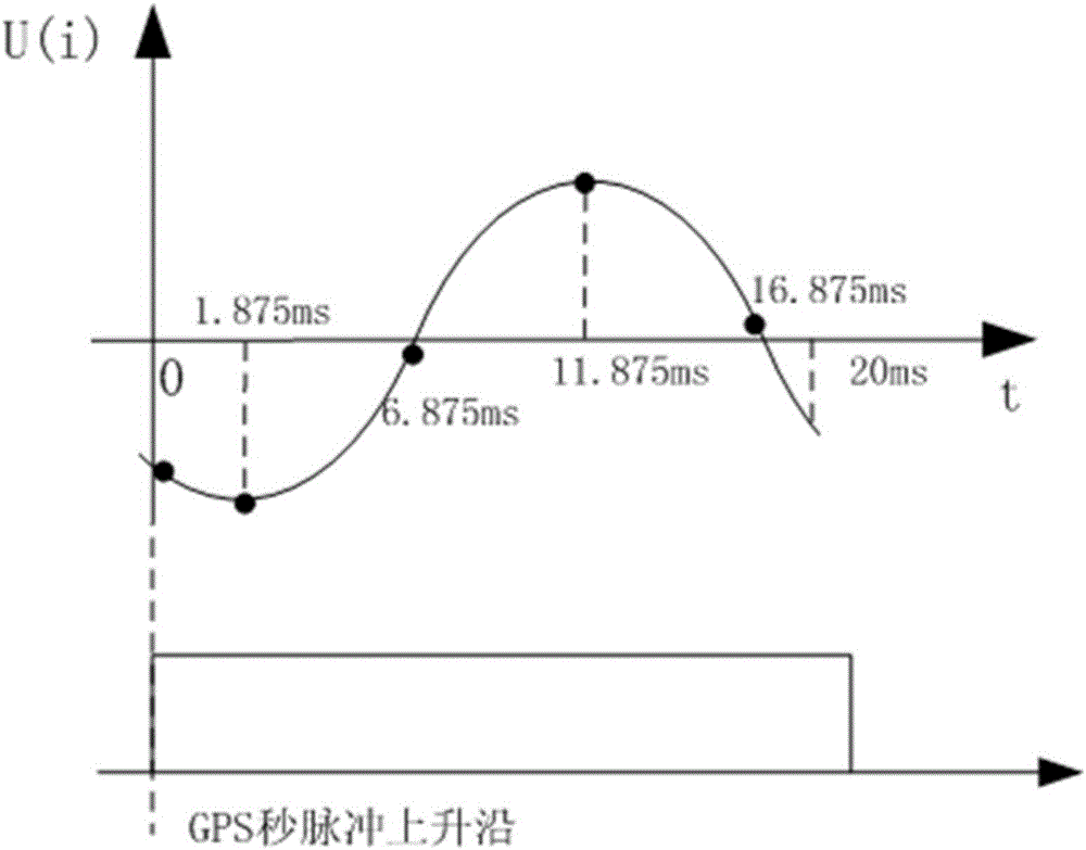
[0027] S2. When the rising edge of the second pulse signal described in step S1 occurs, the communication unit sends a synchronization command to the indicator, and controls each indicator to simultaneously sample the voltage waveform of the phase sequence installed separately;

[0028] The communication unit sends the broadcast synchronization command through micro-power wireless: since the three indicators receive the broadcast synchronization signal at the same time, record the synchronization time as the starting time, start recording the data of the sampling point, and continuously record the data of 3 cycles; If the cycle ...


PUM


Abstract

The invention discloses an identification method of a fault indicator installation phase sequence, which includes the steps of: monitoring a second pulse signal rising edge of a GPS clock signal; sending synchronization commands to indicators by a communication unit when the second pulse signal rising edge appears, and controlling each indicator to carry out voltage waveform sampling on respectively-installed phase sequence; and copying and reading sampling data of each indicator, and judging the phase sequence installed on each indicator according to a phase relationship of a three-phase voltage of an electric power system. The identification method of the fault indicator installation phase sequence uses the GPS clock signal to provide the uniform synchronization signal, uses the synchronization signal to control each indicator for the voltage waveform sampling, and judges the phase sequences where the indicators are according to the sampling waveforms. Therefore the method is automatically realized through the fault indicators all the way without human intervention. The efficiency is extremely high. The mistakes and errors possibly brought by manual operation are avoided. The information of the phase sequences where the indicators are is re-checked and corrected regularly and irregularly. The information correctness of the phase sequences where the indicators are is guaranteed.

Description

technical field [0001] The invention specifically relates to a method for identifying the installation phase sequence of a fault indicator. Background technique [0002] With the development of national economy and technology and the improvement of people's living standards, electric energy has become one of the indispensable energy sources in people's production and life. [0003] Power equipment status online monitoring technology has been widely used in power systems because of its advantages of automatic monitoring of power system operation status, automatic detection of power equipment failures and active reporting of alarm information. On-line monitoring fault indicator is one of the important equipment of power system automation technology. It generally consists of 1 communication unit and 3 communication fault indicators. The indicator communicates with the communication unit through micro-power wireless, and the 3 indicators It is also possible to communicate with ...

Claims


Application Information

Patent Timeline
IPC IPC(8): G01R29/18
CPCG01R29/18
Inventor 许健阳武文江林李绍文陈观强
Owner WILLFAR INFORMATION TECH CO LTD
Why Eureka
Try Eureka