Related waveform design method for MIMO radar part based on LFM fundamental wave beam

A technology of partial correlation and waveform design, applied in the field of MIMO radar, it can solve the problems of main lobe energy loss, high side lobes, inability to approximate the desired pattern well, and achieve strong Doppler tolerance and good approximation effects.

Active Publication Date: 2016-06-22
XIDIAN UNIV
View PDF4 Cites 8 Cited by
  • Summary
  • Abstract
  • Description
  • Claims
  • Application Information

AI Technical Summary

Problems solved by technology

This method is based on the linear frequency modulation LFM signal for waveform design, so it has strong Doppler tolerance, but the side lobe of the transmission pattern is high, and the energy of the main lobe has a certain loss, so it cannot approach the desired direction map

Method used


Image

  • Related waveform design method for MIMO radar part based on LFM fundamental wave beam
  • Related waveform design method for MIMO radar part based on LFM fundamental wave beam
  • Related waveform design method for MIMO radar part based on LFM fundamental wave beam

Examples


Embodiment Construction

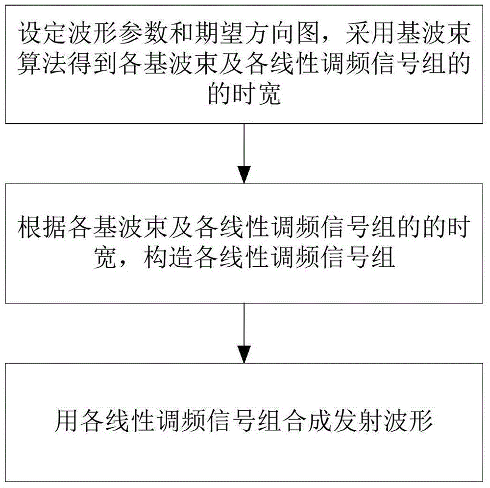
[0018] refer to figure 1 , the implementation steps of the present invention are as follows:

[0019] Step 1, obtain the time width of the fundamental beam and the chirp signal group.

[0020] Set the number of waveforms, waveform bandwidth, waveform time width and desired pattern, and obtain I basic beam b by the basic beam algorithm i (θ) and I base signal sampling points Num i , by the number of base signal sampling points Num i Calculate the time width of I chirp signal group with waveform time width T T i = T × Num i / Σ i = 1 I Num i , i=1,2,...,I, θ is the airspace angle.

[0021] Step 2, using the fundamental beam and the time width of the chirp signal group to construct the chirp signal group:

[0022] 2a) Betwee...


PUM


Abstract

The invention discloses a related waveform design method for an MIMO radar part based on an LFM fundamental wave beam, and mainly solves a problem that the transmission directional diagram performance of waveform and the Doppler tolerance cannot be considered at the same time in the prior art. The method comprises the implementation steps: setting a waveform parameter and an expected directional diagram, and obtaining all fundamental wave beams and the time width of each chirp signal group; constructing all chirp signal modules according to the fundamental wave beams and the time width of each chirp signal group; and synthesizing a transmission waveform through the combination of all chirp signal groups. According to the invention, the method constructs a transmission directional diagram close to the chirp signal groups of the fundamental wave beams, synthesizes the transmission waveform through the combination of all chirp signal groups, enables the transmission directional diagram of the waveform to be able to approach the expected directional diagram, guarantees that the waveform has higher Doppler tolerance, and can be used for the design of the transmission waveform of the MIMO radar.

Description

technical field [0001] The invention belongs to the technical field of MIMO radar, and specifically relates to a method for designing partly correlated waveforms, which can be used for rational configuration of MIMO radar transmission energy. Background technique [0002] Multiple-input multiple-output MIMO radar is a new system radar with multiple transmitting and receiving antennas. Each transmitting antenna can flexibly transmit different waveforms, which has the advantage of waveform diversity. According to the correlation between waveforms, the transmitted waveforms can be divided into two types: orthogonal waveforms and partially correlated waveforms. For orthogonal waveforms, the waveforms are orthogonal to each other, and the transmitted energy is evenly distributed throughout the spatial region. For partially correlated waveforms, each waveform has a certain correlation. By designing a partially correlated waveform that satisfies the desired pattern, the transmitte...

Claims


Application Information

Patent Timeline
Patent Type & Authority Applications(China)
IPC IPC(8): G01S7/02
CPCG01S7/02
Inventor 赵永波李慧程增飞刘宏伟苏洪涛何学辉冯大政
Owner XIDIAN UNIV
Why Eureka
Try Eureka