A high-speed large scene phase recovery data acquisition device illuminated by natural light

A technology of natural light illumination and phase recovery, applied in the direction of using optical devices, measuring devices, optics, etc., can solve the problems of unable to meet the requirements of data acquisition, complex interference devices, reducing system practicability, etc., to improve the speed of data acquisition, avoid The effect of mechanical movement

Active Publication Date: 2018-03-20
ANHUI UNIVERSITY
View PDF7 Cites 2 Cited by
  • Summary
  • Abstract
  • Description
  • Claims
  • Application Information

AI Technical Summary

Problems solved by technology

However, the interferometry method has at least the following disadvantages: (1) The wave field enters the sensor area along different independent paths, and the measurement results will be severely damaged by vibration (caused by environmental interference); (2) The temporal coherence of the light source is very high, This requires a more complex interferometric device, etc.
Although these methods avoid mechanical movement, they all require special imaging components, the former requires a volume holography device, and the latter requires a flow cytometer, which reduces the practicality of the system
[0010] On the other hand, the basic principle of traditional cameras is the theory of pinhole imaging, and its resolution is limited by the size and precision of the focal plane array. In order to obtain images with higher pixels, we can only try to reduce the minimum size of the focal plane array.
This method has reached a bottleneck state at present, resulting in huge challenges in data acquisition, processing, storage and transmission of larger scale and wider dynamic range. Requirements for data acquisition when performing object phase recovery in

Method used


Image

  • A high-speed large scene phase recovery data acquisition device illuminated by natural light
  • A high-speed large scene phase recovery data acquisition device illuminated by natural light
  • A high-speed large scene phase recovery data acquisition device illuminated by natural light

Examples


Embodiment Construction

[0022] The present invention will be further described below in conjunction with the accompanying drawings and specific embodiments.

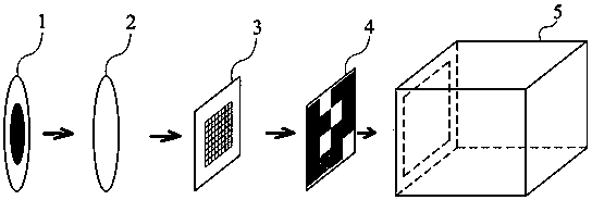
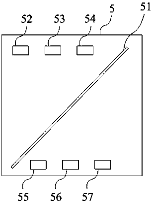
[0023] Such as figure 2 As shown, a high-speed large-scene phase recovery data acquisition device illuminated by natural light includes a band-pass filter 1 , a polarizer 2 , a spatial light modulator 3 , an LCD display 4 and a CCD array 5 . The polarizer 2 is arranged on the outgoing light path of the bandpass filter 1, the spatial light modulator 3 is arranged on the outgoing light path of the polarizer 2, the LCD display screen 4 is arranged on the transmission light path of the spatial light modulator 3, and the CCD array 5 is arranged on the The transmitted light path of the LCD display screen 4 . The spatial light modulator 3 is a phase type. The CCD array 5 internally includes a beam splitter 51 and a plurality of three-color CCD image sensors 52, 53, 54, 55, 56 and 57, wherein the CCD image sensors 52, 53 and 54 are arranged on the r...


PUM


Abstract

The invention provides a high-speed large-scene phase recovery data acquisition device illuminated by natural light, which includes a bandpass filter, a polarizer, a spatial light modulator, an LCD display screen, and a CCD array; the polarizer is arranged at the outlet of the bandpass filter On the outgoing light path, the spatial light modulator is arranged on the outgoing light path of the polarizer, the LCD display screen is arranged on the outgoing light path of the spatial light modulator, and the CCD array is arranged on the outgoing light path of the LCD display screen. The present invention can avoid the mechanical movement introduced by collecting intensity images in the traditional phase recovery, and improves the data collection speed; at the same time, the introduction of the idea of ​​compressible sensing enables the present invention to obtain the same data as the traditional camera in the case of a small amount of data collection. The acquisition effect is excellent, and the whole device can meet the data acquisition requirements of phase recovery in high-speed and large scenes.

Description

technical field [0001] The invention relates to the technical fields of optical measurement and imaging, in particular to a high-speed large scene phase recovery data acquisition device illuminated by natural light. Background technique [0002] The complete light field contains information such as intensity, wavelength and phase. Phase information is more important than intensity information, and its importance is particularly prominent in the fields of optical measurement, adaptive optics, microscopy, biomedicine, and X-ray optics. Unfortunately, the oscillation frequency of the light field is too high. Both the human eye and existing optical detection instruments can only record the intensity information of the light field, but cannot directly record the phase information of the light field. [0003] The most classical phase measurement method is interferometry. However, interferometry has at least the following disadvantages: (1) The wave field enters the sensor area a...

Claims


Application Information

Patent Timeline
Patent Type & Authority Patents(China)
IPC IPC(8): G02B27/00H04N5/225G01B11/00
CPCG02B27/00G01B11/00H04N23/00
Inventor 程鸿沈川张成吕倩倩陈娅萍
Owner ANHUI UNIVERSITY
Why Eureka
Try Eureka