Eureka AIR delivers breakthrough ideas for toughest innovation challenges, trusted by R&D personnel around the world.

Method for curved surface thermal-error compensation of whole workbench of precise numerical-controlled machine tool

A precision numerical control and compensation method technology, applied in the direction of program control, computer control, general control system, etc., can solve the problems of thermal error compensation efficiency uncertainty, occupying workbench space area, workbench flatness error, etc., to achieve guaranteed Authentic effectiveness, enhanced functionality and precision, high stability effects

Active Publication Date: 2016-06-22
HEFEI UNIV OF TECH
View PDF7 Cites 23 Cited by
  • Summary
  • Abstract
  • Description
  • Claims
  • Application Information

AI Technical Summary

Problems solved by technology

[0004] However, in actual mechanical processing, the workpiece has a certain volume shape and occupies a certain space area of ​​the workbench.
There are flatness errors in the workbench itself, and there are differences in the spatial coordinates of each point on the workbench. At the same time, the workbench is connected with the guide rail through the slider, and the thermal deformation law is dynamic and complex.
According to the thermal error compensation technology implemented by the national standard ISO230-3:2007, the current scientific research personnel only use the thermal error in the Z-axis direction of a certain fixed point of the workbench to replace the thermal error of each point in the whole workbench range, ignoring the thermal error in the whole workbench range. The impact of the difference of thermal errors at each point on the machining accuracy has led to a large uncertainty in the thermal error compensation model established based on the single point of the workbench for the Z-axis axial thermal error compensation within the entire workbench of the machine tool.

Method used


Image

  • Method for curved surface thermal-error compensation of whole workbench of precise numerical-controlled machine tool
  • Method for curved surface thermal-error compensation of whole workbench of precise numerical-controlled machine tool
  • Method for curved surface thermal-error compensation of whole workbench of precise numerical-controlled machine tool

Examples


Embodiment 1

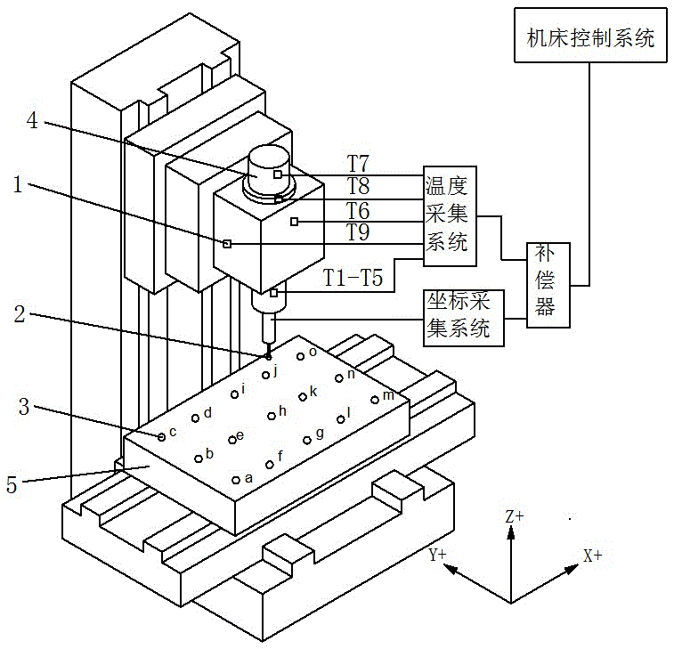
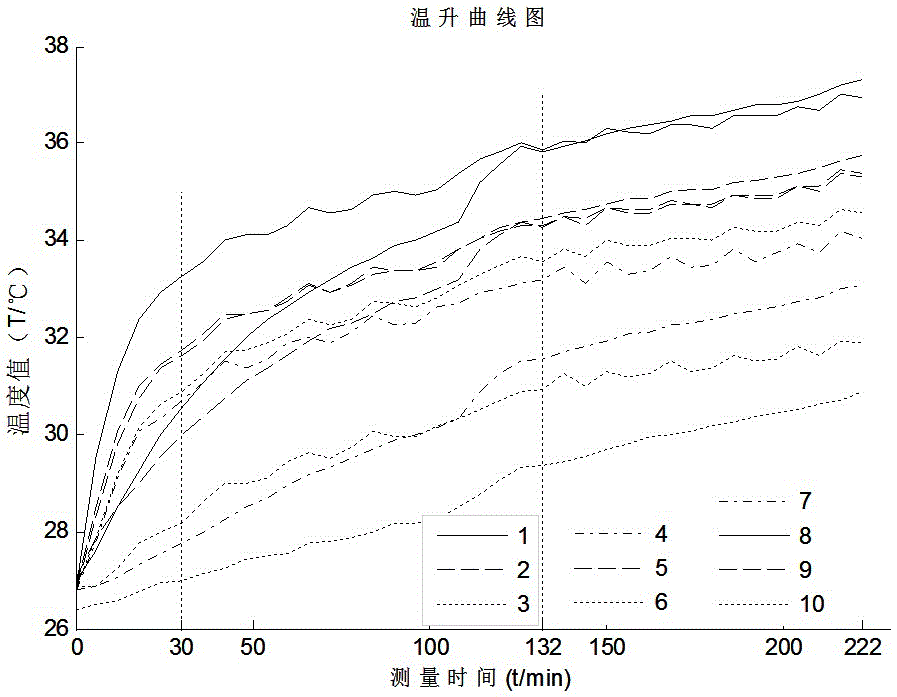
[0041] In this embodiment, the Leaderway-V450 CNC machining center is selected. During the experiment, the main shaft 4 rotates at a constant speed of 6000 rpm, the main shaft 4 is fed at 1500 mm / min, and the main shaft 4Z is idling while the table 5 is running back and forth around the X and Y axes. , workbench 5 feeds at 400mm / min, collects the temperature and coordinates of different positions of workbench 5 below spindle 4 every 5 minutes, and takes 1 minute to measure 15 points each time according to the numbering sequence of measuring point 3. The duration is 4+ hours. The experiment is divided into two batches, the first batch is modeling experiment, ambient temperature: 26.12-30.75°C; the second batch is verification experiment, ambient temperature: 26.38-30.88°C.

[0042] Below are the specific implementation steps of this embodiment:

[0043] The first step: Use the temperature acquisition system to measure the temperature values ​​of the 4 key parts of the machine ...


PUM


Abstract

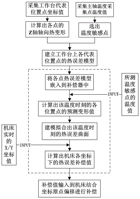
The invention relates to a method for curved surface thermal-error compensation of the whole workbench of a precise numerical-controlled machine tool. The method includes acquiring the temperature information of key positions of main shafts of the machine tool and Z-axis coordinate information of representative position point of a workbench, screening temperature sensitive points, establishing a thermal-error model of all measuring points in a workbench scope, embedding the established thermal-error model of all measuring points in a compensator, calculating a predicted thermal deflection of all measuring points at the current temperature and current moment, carrying out curved surface modeling for predicted thermal deflection of all measuring points at the current temperature and current moment, establishing a whole workbench curved surface thermal-error compensation model, calculating the thermal error compensation value of the machine tool at the coordinate position, inputting the obtained compensation value to the machine tool, and realizing Z-axis axial thermal error real-time compensation in the whole workbench scope of the machine tool by combining true origin offset. Modeling and predicting Z-axis axial thermal error of the whole workbench scope are carried out, so that accurate Z-axis axial thermal error compensation value in the whole workbench scope is obtained.

Description

technical field [0001] The invention relates to the technical field of precision machining machine tools, in particular to a method for compensating the thermal error of the full workbench surface of a precision numerical control machine tool. Background technique [0002] In the machining process of CNC machine tools, due to the influence of multiple factors such as ambient temperature, spindle rotation, and cutting parameters, CNC machine tools have the characteristics of multiple heat sources and complex and changeable temperature fields, resulting in the work of installing the spindle end of the cutting tool and installing the workpiece. The change of the relative position of the stage is finally passed on to the machining error of the part. By sampling the finite temperature points of the CNC machine tool, establishing a thermal error compensation model to predict the thermal error value, and the software thermal error compensation control technology that compensates in...

Claims


Application Information

Patent Timeline
IPC IPC(8): G05B19/404
CPCG05B19/404
Inventor 苗恩铭徐建国董云飞魏新园
Owner HEFEI UNIV OF TECH
Why Eureka
Eureka Blog
Learn More