
Flight device control system, control method and aerial photographing UAV (Unmanned Aerial Vehicle)

A flying device and control system technology, applied in the field of aerial photography drones, can solve problems such as self-portrait, automatic follow cannot fully meet various flexible creation needs, and complex operation, so as to avoid tediousness, improve service life, Effects of Simplified Control Techniques

Inactive Publication Date: 2016-06-22
成都第二记忆科技有限公司
View PDF7 Cites 20 Cited by
  • Summary
  • Abstract
  • Description
  • Claims
  • Application Information

AI Technical Summary

Problems solved by technology

[0010] So the disadvantage of pure manual operation is: the operation is complicated, requires two professionals to operate, and cannot take selfies
[0011] (2) Insufficiency of automatic follow-up
But there are still many deficiencies, the main problem is: fully automatic follow can not fully meet the various flexible creative needs of users in shooting

Method used


Image

  • Flight device control system, control method and aerial photographing UAV (Unmanned Aerial Vehicle)
  • Flight device control system, control method and aerial photographing UAV (Unmanned Aerial Vehicle)
  • Flight device control system, control method and aerial photographing UAV (Unmanned Aerial Vehicle)

Examples


Embodiment Construction

[0046] The following will clearly and completely describe the technical solutions in the embodiments of the present invention with reference to the accompanying drawings in the embodiments of the present invention. Obviously, the described embodiments are only some, not all, embodiments of the present invention. Based on the embodiments of the present invention, all other embodiments obtained by persons of ordinary skill in the art without creative efforts fall within the protection scope of the present invention.

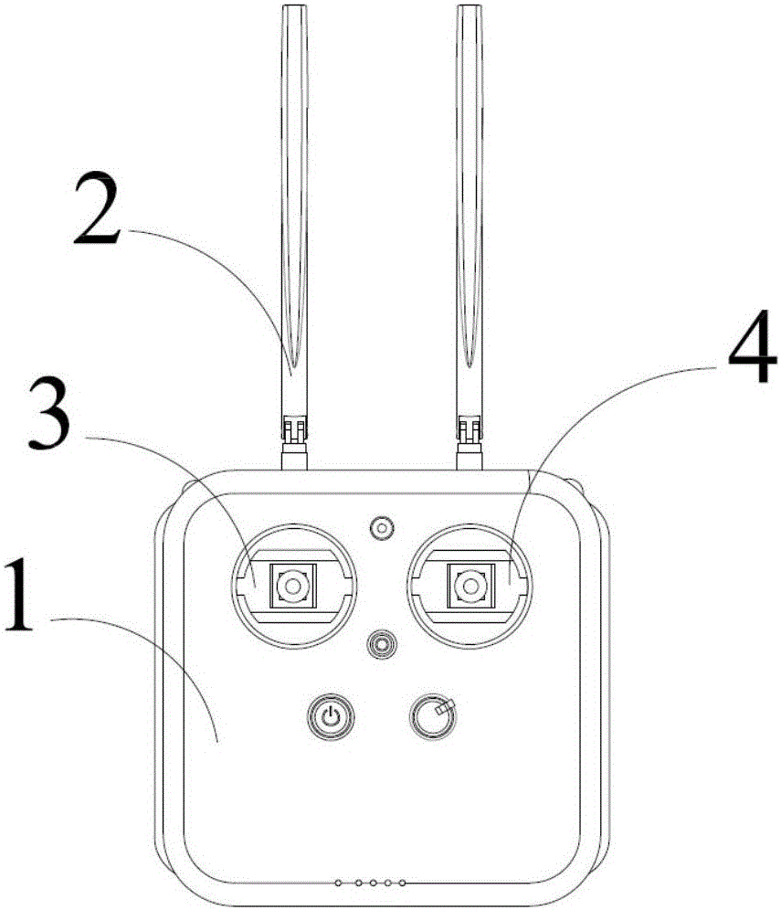
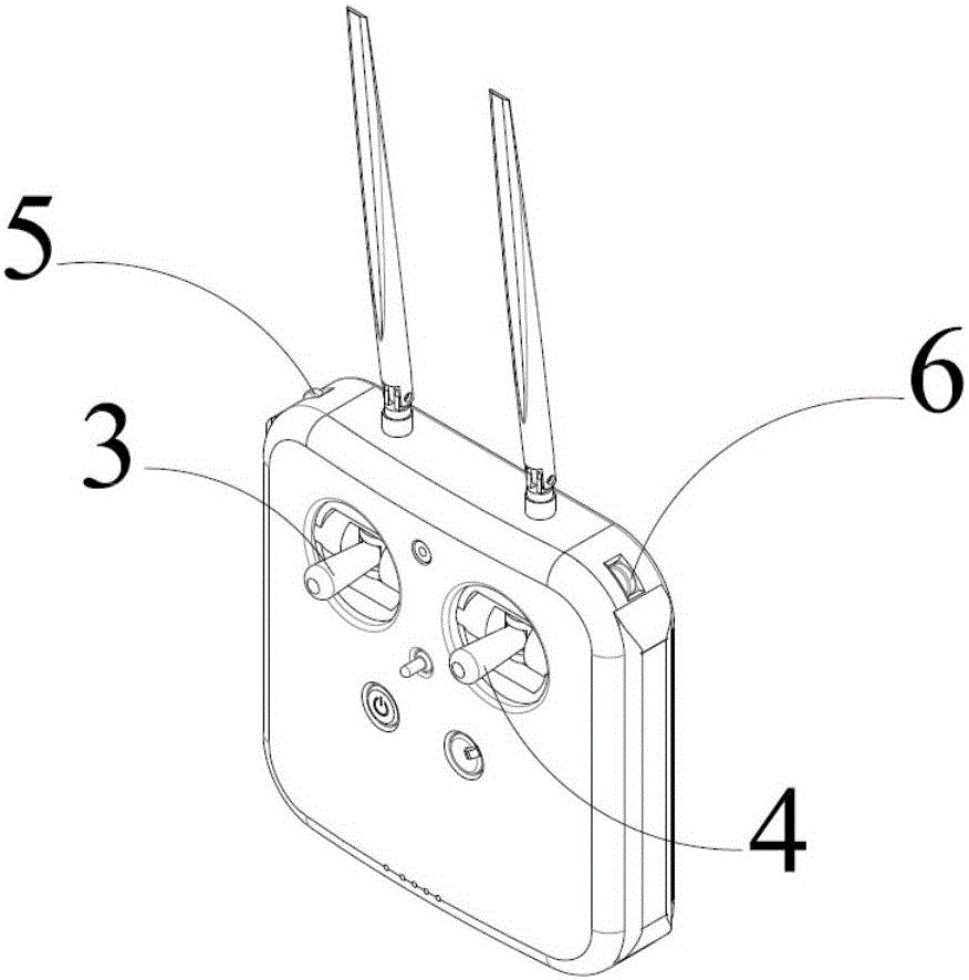
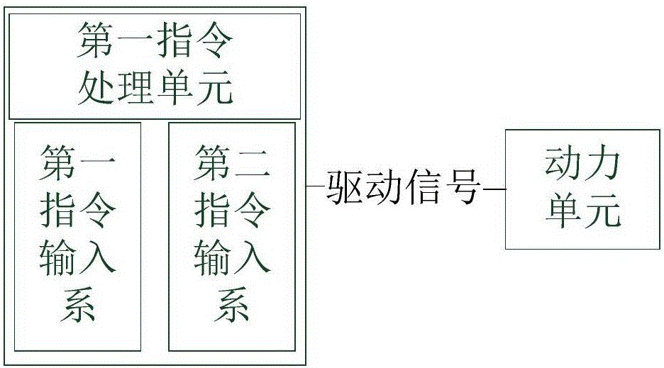
[0047] Such as image 3 , Figure 4 , Figure 5 and Figure 6 As shown, a flying device control system of the present invention includes a command processing unit for converting control commands into driving signals for controlling the movement of the power unit of the flying device, and the command processing unit includes a first command input system and a second command input system. Input system; the driving signal can be a power signal used to directly driv...


PUM


Abstract

The invention provides a flight device control system. The flight device includes a first command processing unit used for converting control commands to driving signals controlling movement of a power unit of a flight device. The command processing unit includes a first command input system and a second command input system. The system also includes a console control system comprising a second command processing unit and a movement assembly. The second command processing unit is used for outputting commands for controlling the movement assembly to adjust the facing direction of a console camera and adjust the console camera in real time for keeping a to-be-shot body in a predetermined area of a shooting frame. The console camera can rotate in 360 degrees in the horizontal direction. According to the invention, complex flight device control commands are distributed to the first command input system and the second command input system reasonably and the second command system is set for manually inputting a part of flight device movement commands.

Description

technical field [0001] The invention belongs to the technical field of automatic control, and relates to the control technology of a flight device, in particular to a control system and a control method of a flight device and an aerial photography unmanned aerial vehicle including the control system. Background technique [0002] With the maturity of technology, flying devices such as drones and airships have gradually penetrated into daily life. Moreover, the aerial photography market formed by the combination of the flying device with its unique viewing angle and photography and camera technology has attracted much attention and popularity. [0003] However, the complexity of the control of 3D flying devices has increased the technical threshold for the popularization of this technology. Taking the aircraft controlled by the traditional pure manual remote control method as an example, to complete the control of all degrees of freedom of the aircraft, at least the remote c...

Claims


Application Information

Patent Timeline
IPC IPC(8): G05D1/08G05D1/12G05D3/12
CPCG05D1/0808G05D1/12G05D3/12
Inventor 吴嘉伟
Owner 成都第二记忆科技有限公司
Learn More