DSP-based emergency lane monitoring system and realizing method thereof

A technology of emergency lanes and implementation methods, which is applied in the field of computer vision, can solve the problems of inability to realize real-time detection, destroy road buried coils, and low efficiency of manual processing, and achieve the effect of reducing human resource investment, reducing casualties, and saving capture time

Inactive Publication Date: 2016-06-22
CHENGDU UNIVERSITY OF TECHNOLOGY
View PDF8 Cites 10 Cited by
  • Summary
  • Abstract
  • Description
  • Claims
  • Application Information

AI Technical Summary

Problems solved by technology

The disadvantages of this method are: a. There are many videos to be viewed, and the efficiency of manual processing is low; b. Human limitations, visual fatigue, etc. cause "missing detection"; c. Manual processing cannot realize real-time detection and timely reminders
[0004] With the rapid development of computer vision, intelligent video analysis technology has been vigorously promoted and used in the field of traffic security. However, almost all of the current intelligent monitoring technologies use the method of triggering snapshots. The principle is to detect vehicle violations through relevant detection technologies. Then trigger to take pictures and leave proofs, including microwave detection, infrared detection, magnetometer detection, induction coil detection, etc., and these detections must either destroy the road buried coil, or install related transmitting equipment, and are greatly affected by the environment. Increased costs and impacted performance

Method used


Image

  • DSP-based emergency lane monitoring system and realizing method thereof
  • DSP-based emergency lane monitoring system and realizing method thereof
  • DSP-based emergency lane monitoring system and realizing method thereof

Examples


Embodiment

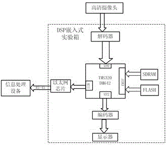
[0038] Such as figure 1 Shown, a kind of emergency lane monitoring system based on DSP, comprises the high-definition camera, DSP embedded experiment box and information processing equipment connected with data transmission mode successively; Described DSP embedded experiment box comprises DSP chip, is connected with DSP chip decoder, encoder, Ethernet chip, and a display connected to the encoder; the high-definition camera is connected to the decoder, and the information processing device is connected to the Ethernet chip through an RJ-45 interface; the high-definition camera It is installed in a place where the internal image of the emergency lane and the identification line can be collected at the same time, and the single picture of the video image frame collected by it meets the basic conditions for license plate recognition.

[0039] In this embodiment, the high-definition camera adopts a CCD camera, the DSP chip adopts TMS320DM642, the decoder adopts TVP5150, the encode...


PUM


Abstract

The invention discloses a DSP-based emergency lane monitoring system and a realizing method thereof. The DSP-based emergency lane monitoring system comprises a high-resolution camera, a DSP embedded experiment box and information processing equipment, wherein the high-resolution camera, the DSP embedded experiment box and the information processing equipment are successively connected in a data transmission manner. The high-resolution camera is mounted at a position where an image in the emergency lane and identification lines can be simultaneously acquired. Furthermore the single picture of the acquired video image frame has basic conditions for identifying a license plate. Lane identification line edge detection is performed on an input monitoring video flow, and then image dividing is performed. Vehicle determining is performed on an emergency lane area which is reserved after dividing. If no vehicle exists, image transmission of a next frame is performed. If a vehicle exists, license plate identification is performed. The DSP-based emergency lane monitoring system realizes processing of an acquired video image and directly identifies a fact whether the vehicle in the emergency lane breaks a role without snapshot, thereby saving snapshot time and improving real-time performance of a road monitoring system.

Description

technical field [0001] The invention relates to the technical field of computer vision, in particular to a DSP-based emergency lane monitoring system and an implementation method. Background technique [0002] The emergency lane on the expressway is a special passage for vehicles dealing with emergency affairs such as engineering rescue, fire rescue, medical rescue or civilian police performing emergency official duties. Article 82 of the "Regulations for the Implementation of the Road Traffic Safety Law of the People's Republic of China" stipulates: When a motor vehicle is driving on an expressway, it is not allowed to drive or stop in the emergency lane unless it is an emergency. However, nowadays, many drivers ignore this regulation, especially in the case of expressway congestion caused by emergencies. In order to buy a little time, many drivers often illegally occupy the emergency lane, which makes it impossible for various emergency vehicles to pass the emergency lane....

Claims


Application Information

Patent Timeline
Patent Type & Authority Applications(China)
IPC IPC(8): G08G1/017H04N7/18G06K9/00
CPCH04N7/18G08G1/0175G06V20/584G06V20/625
Inventor 刘明哲赵成强左卓于欢赵越陈旭
Owner CHENGDU UNIVERSITY OF TECHNOLOGY
Why Eureka
Try Eureka