
A permanent magnet coupling speed regulating device with axial meshing area adjustment

A technology of meshing area and permanent magnetic coupling, which is applied in the field of coupling speed regulation, can solve problems such as high technical requirements, insufficient system reliability, and low energy conversion efficiency, and achieve the effect of broad market application prospects

Active Publication Date: 2018-06-01
江苏达锐斯永磁传动科技有限公司
View PDF4 Cites 0 Cited by
  • Summary
  • Abstract
  • Description
  • Claims
  • Application Information

AI Technical Summary

Problems solved by technology

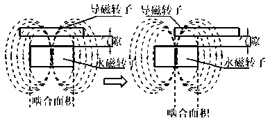
[0007] In view of the shortcomings of current various speed regulating devices such as low energy conversion efficiency, insufficient system reliability, high technical requirements, and strict environmental requirements, the present invention firstly proposes a permanent magnet coupling speed regulating device with axial meshing area adjustment, Through the original axial adjustment mechanism to adjust the relative position of the permanent magnet rotor assembly and the magnetic rotor assembly in the horizontal direction of the axis to change the meshing area of ​​interaction, and then change the torque transmitted between the magnetic rotor assembly and the permanent magnet rotor assembly , to achieve the transformation of the load speed, to achieve the purpose of speed regulation and energy saving

Method used


Image

  • A permanent magnet coupling speed regulating device with axial meshing area adjustment
  • A permanent magnet coupling speed regulating device with axial meshing area adjustment
  • A permanent magnet coupling speed regulating device with axial meshing area adjustment

Examples


Embodiment Construction

[0042] The technical solutions of the present invention will be described in detail below in conjunction with the accompanying drawings, so that those skilled in the art can understand the present invention more clearly, but the protection scope of the present invention is not limited thereby.

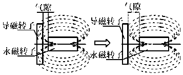
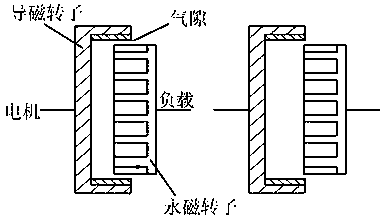
[0043] At first explain the technical principle of the present invention, simultaneously in conjunction with appendix figure 1 to attach image 3 , with figure 1 It is the schematic diagram of the existing air-gap adjustable permanent magnet speed governor. The adjustment of the speed is realized by adjusting the air gap between the magnetically permeable rotor and the permanent magnet rotor. The adjustment mechanism of the air gap is relatively complicated and based on The accuracy of speed adjustment by air gap adjustment is low. The permanent magnetic coupling speed regulating device innovatively proposed by the present invention realizes the adjustment of the rotational speed by ...


PUM


Abstract

The invention provides a permanent magnet coupling speed regulation apparatus with an adjustable axial meshed area. The permanent magnet coupling speed regulation apparatus comprises a magnetic conductive rotor assembly, a permanent magnet rotor assembly, a bearing base assembly, a drive screw assembly, a gear box assembly and a speed regulation output shaft, wherein an inner cylinder is formed at one end of the magnetic conductive rotor assembly; the permanent magnet rotor assembly can extend into the inner cylinder; a fixed air gap is formed between the outer wall surface of the permanent magnet rotor assembly and the inner cylinder wall surface of the magnetic conductive rotor assembly; the permanent magnet rotor assembly is mounted on the bearing base assembly, capable of circumferentially rotating relative to the bearing base assembly and capable of synchronously and axially moving along with the bearing base assembly; one end of the drive screw assembly is fixedly connected with the bearing base assembly while the other end of the drive screw assembly is in threaded connection with the gear box assembly; the gear box assembly can drive the drive screw assembly to axially move; and the front part of the speed regulation output shaft is connected with the permanent magnet rotor assembly through a spline while the lower part of the speed regulation output shaft is mounted on the gear box assembly. The permanent magnet coupling speed regulation apparatus provided by the invention can carry out stepless smooth speed regulation according to loads, so that the permanent magnet coupling speed regulation apparatus is high in market prospects.

Description

technical field [0001] The invention relates to the technical field of coupling speed regulation, in particular to an axial meshing area adjustment type permanent magnet coupling speed regulation device. Background technique [0002] my country is a country with a large energy consumption, and the energy reserve is insufficient, and the energy utilization rate is low. Energy saving and consumption reduction have become the focus of the whole society. The loads of fans and pumps are commonly used equipment with a large volume and a wide range, and their energy consumption accounts for a large proportion of the total energy consumption of AC motors. The electricity consumption of the electric motor system accounts for about 60% of the national electricity consumption, of which the electricity consumption of fans accounts for 10.4% of the total electricity consumption of the country, pump motors account for 20.9%, compressors account for 9.4%, and air-conditioning refrigerators...

Claims


Application Information

Patent Timeline
Patent Type & Authority Patents(China)
IPC IPC(8): H02K49/10
CPCH02K49/102
Inventor 李新勇
Owner 江苏达锐斯永磁传动科技有限公司
Learn More