A method and device for data transmission

A technology of data transmission and transmission block, applied in the direction of digital transmission system, separation device of transmission path, transmission system, etc., can solve the problems of real-time and low reliability.

Active Publication Date: 2019-09-17
DATANG MOBILE COMM EQUIP CO LTD
View PDF7 Cites 0 Cited by
  • Summary
  • Abstract
  • Description
  • Claims
  • Application Information

AI Technical Summary

Problems solved by technology

[0006] The present invention provides a method and equipment for data transmission, which is used to solve the problem of low real-time performance and reliability in the current wireless communication system transmission mode existing in the prior art

Method used


Image

  • A method and device for data transmission
  • A method and device for data transmission
  • A method and device for data transmission

Examples


example 1

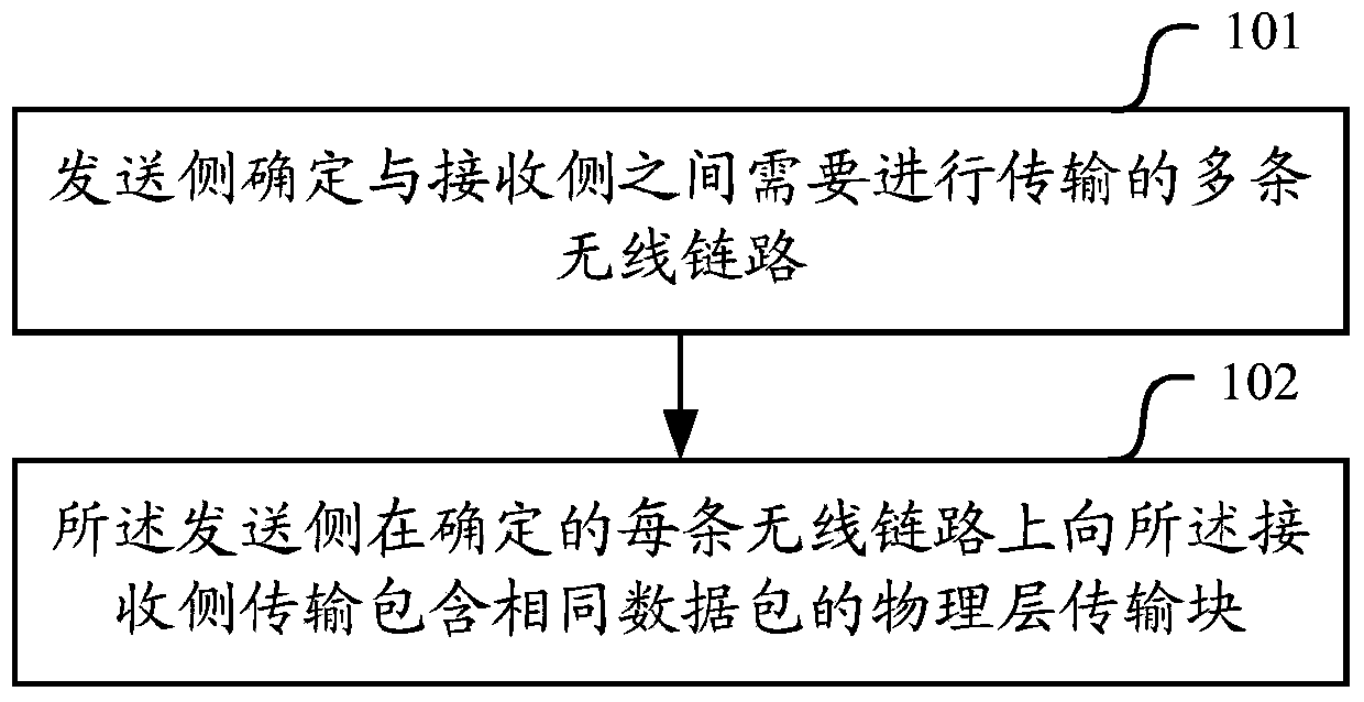
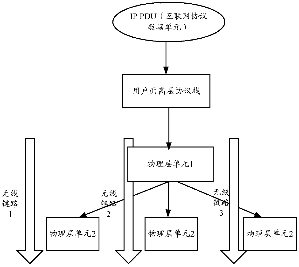
[0218] Example 1: Multi-channel transmission (downlink transmission) under the same base station.

[0219] correspond figure 2 protocol stack architecture.

[0220] Step 1: The base station physical layer unit 1 performs physical layer processing (adding CRC, channel coding, multiplexing, interleaving, etc.) to the MAC PDU from the upper layer protocol stack to form physical layer transmission blocks of different redundancy versions (RV);

[0221] Step 2: The physical layer unit 1 of the base station distributes the physical layer transmission block to different physical layer units 2 according to the scheduling transmission rules, and the different physical layer units 2 belong to different cells;

[0222] Step 3: The main cell of the base station sends a multiplex transmission scheduling command to the UE, and the physical layer units 2 of different cells send redundant physical layer transmission data to the UE on different wireless links;

[0223] Step 4: UE receives th...

example 3

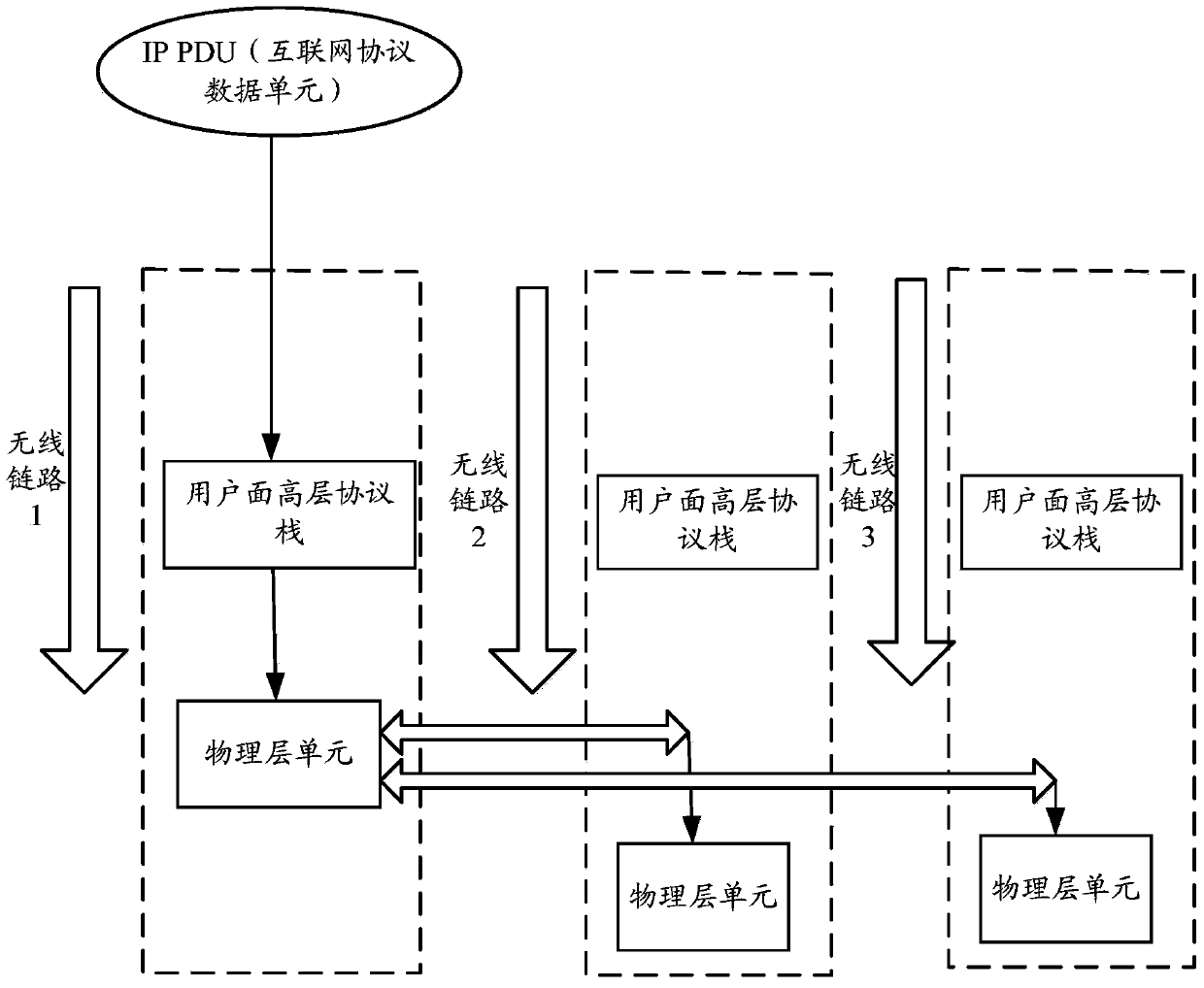
[0233] Example 3: Multi-channel transmission (downlink transmission) under different base stations.

[0234] correspond image 3 Protocol stack architecture2.

[0235] Step 1: The physical layer unit of the main cell performs physical layer processing (adding CRC, channel coding, multiplexing, interleaving, etc.) to the MAC PDU from the upper layer protocol stack to form physical layer transmission blocks of different redundancy versions (RV);

[0236] Step 2: The base station of the main cell distributes the physical layer transmission block to different base stations through the inter-base station interface according to the scheduling transmission rules;

[0237] Step 3: the base station of the main cell sends a multiplex transmission scheduling command to the UE, and different base station cells send physical layer redundant transmission data to the UE on different wireless links;

[0238] Step 4: UE receives the base station scheduling command, and receives the physical ...

example 4

[0241] Example 4: Multi-channel transmission (uplink transmission) under different base stations.

[0242] correspond figure 2 Protocol stack architecture2.

[0243] Step 1: The terminal performs physical layer processing (adding CRC, channel coding, multiplexing, interleaving, etc.) to the MAC PDU from the high-layer protocol stack to form physical layer transmission blocks of different redundancy versions (RV);

[0244] Step 2: The terminal sends the physical layer transport block to the physical layer of different cells on the wireless links of different cells according to the multiplex transmission scheduling command sent by the base station of the primary cell;

[0245] Step 3: The base station participating in the multiplex transmission sends the received physical layer transmission block to the base station of the main cell through the inter-base station interface;

[0246] Step 4: The physical layer unit of the base station of the primary cell decodes the physical l...


PUM


Abstract

The embodiments of the present invention relate to the technical field of wireless communication, and in particular to a method and device for data transmission, which are used to solve the problem in the prior art that the transmission mode of the current wireless communication system is not high enough in real time and reliability. In the embodiment of the present invention, the sending side determines multiple wireless links that need to be transmitted with the receiving side; and transmits a physical layer transmission block containing the same data packet to the receiving side on each determined wireless link. Since the embodiment of the present invention transmits the physical layer transmission block containing the same data packet on different wireless links, the resources of different wireless channels connected at the receiving side can be fully utilized, thereby improving real-time performance and reliability. Compared with the current wireless communication The system can better support the real-time and reliability requirements of new applications such as machine type communication.

Description

technical field [0001] The present invention relates to the technical field of wireless communication, in particular to a method and device for data transmission. Background technique [0002] With the development of the mobile Internet and the Internet of Things, the demand for business data volume has exploded. Massive device connections and diversified Internet of Things services have also brought new technical challenges to mobile communications. The delay and reliability of existing communication systems are designed for human-to-human communication. In terms of delay and reliability, future wireless mobile communication systems must not only continue to better meet the communication needs of human users, but also meet the needs of human users. The real-time and reliability requirements of MTC (Machine Type Communications) promote new applications in industrial fields such as traffic safety, traffic efficiency, and smart grids, so that the concept of a smart society and...

Claims


Application Information

Patent Timeline
Patent Type & Authority Patents(China)
IPC IPC(8): H04L5/00H04L1/00
CPCH04L1/1819H04L5/001H04L5/0044H04W72/23H04W28/04H04W40/02
Inventor 谌丽秦飞康绍莉焦斌
Owner DATANG MOBILE COMM EQUIP CO LTD
Why Eureka
Try Eureka