Method and rotor for producing a short winding head

A winding head and rotor technology, which is applied in the manufacture of winding connectors, windings, and motor generators. It can solve the problems of high-cost assembly steps and achieve the effect of small weight and short structural length.

Active Publication Date: 2016-06-22
SEG AUTOMOTIVE GERMANY GMBH
View PDF5 Cites 6 Cited by
  • Summary
  • Abstract
  • Description
  • Claims
  • Application Information

AI Technical Summary

Problems solved by technology

The prefabrication of the right-angled conductor elements and their subsequent in

Method used


Image

  • Method and rotor for producing a short winding head
  • Method and rotor for producing a short winding head
  • Method and rotor for producing a short winding head

Examples


Embodiment Construction

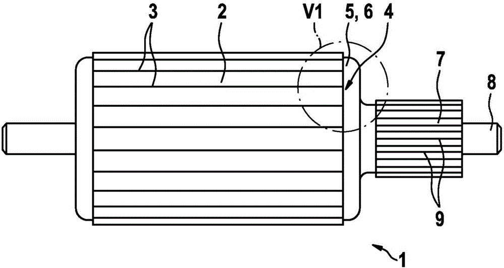
[0021] exist figure 1 The basic structure of the rotor of an electric machine, which can also be referred to as armature or impeller, is shown in , which can be used, for example, as a starter for an internal combustion engine.

[0022] The rotor 1 has a base body 2 composed of a plurality of slotted laminations, resulting in longitudinal slots 3 for receiving electrical conductors forming the windings of the rotor 1 . A winding head 6 formed from a plurality of conductor sections 5 is located on the end face 4 on the right in the drawing of the main body 2 , the conductor end of which winding head is not visible here is introduced into the commutator 7 , which The commutator is likewise fixed on the common shaft 8 of the rotor 1 with the base body 2 . The conductor ends of the conductor section 5 are electrically conductively connected to the contact surface 9 of the commutator 7 .

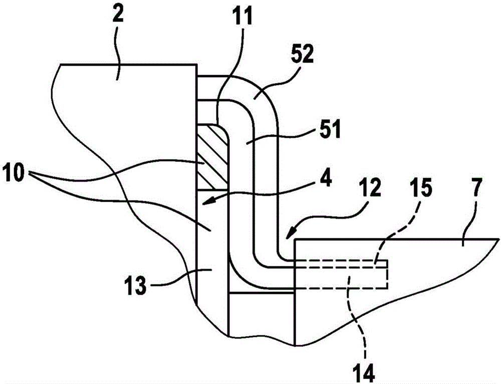
[0023] exist figure 2 is shown enlarged in figure 1 detail diagram of the figure 1 Expr...


PUM


Abstract

The invention relates to a method and a rotor for producing a short winding head (6), in which conductor sections (5) of a rotor winding, emerging on the front side from the base body (2) of a rotor (1), are bent in the direction of a commutator (7). The conductor ends (14, 15) of the conductor sections (51, 52), which are aligned parallel to the axis, are placed in a second inner radial position from an original first outer radial position. Conductor sections (51) leading to the conductor ends (14) are bent over a bending edge (11) of a bending ring (10) placed on the front side on a base body (2) and are aligned at least approximately parallel to the front side (4) of the base body (2).

Description

technical field [0001] The invention relates to a method for producing short winding ends according to the preamble of claim 1 and a rotor having the features of claim 9 for carrying out the method. Background technique [0002] In order to be able to realize the overall length of an electric machine with a rotor with a commutator with the smallest possible overall length, it is aimed to form the winding head as flat as possible between the lamination pack (Lamellenpaket) forming the basic body of the rotor and the commutator. department. The conductors of the rotor winding exiting the base body at the end face are soldered or welded to the commutator, also known as the commutator, at the conductor ends. [0003] In order to form the conductors into windings in the desired connection, the conductors must be connected to the commutator in a defined manner. The ends of the individual conductors protruding from the main body of the rotor have to be brought by overlapping and ...

Claims


Application Information

Patent Timeline
IPC IPC(8): H02K15/00H02K15/08H02K3/51H02K13/04H01R39/32
CPCH01R39/32H02K3/51H02K13/04H02K15/0056H02K15/08H01R2201/10
Inventor W·绍尔A·库德勒科
Owner SEG AUTOMOTIVE GERMANY GMBH
Why Eureka
Try Eureka