An artificial lumbar facet joint system

A technology of facet joints and joints, applied in the direction of spinal implants, etc., can solve the problems of increasing the motion load of adjacent segments, aggravating vertebral body degeneration of adjacent segments, etc., and achieve the effect of ensuring stability

Active Publication Date: 2017-06-13
SOUTHERN MEDICAL UNIVERSITY
View PDF7 Cites 0 Cited by
  • Summary
  • Abstract
  • Description
  • Claims
  • Application Information

AI Technical Summary

Problems solved by technology

However, due to the disappearance of the mobility of the vertebral body of the corresponding segment after spinal fusion, this will inevitably increase the motion load of the adjacent segment, which will lead to the aggravation of the degeneration of the vertebral body of the adjacent segment

Method used


Image

  • An artificial lumbar facet joint system
  • An artificial lumbar facet joint system
  • An artificial lumbar facet joint system

Examples


example 1

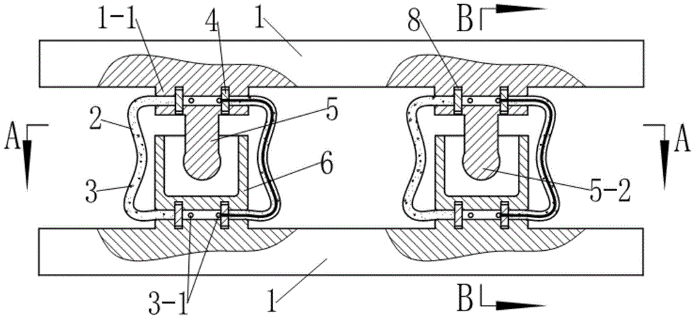
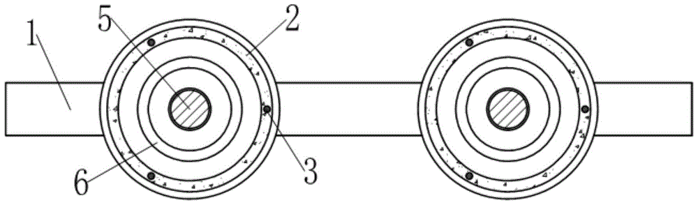
[0025] see Figure 1~6 , the artificial lumbar facet joint system in this example includes two connecting rods 1 straddling the pedicles on both sides of the same lumbar vertebra and a two-joint prosthesis arranged between the two connecting rods 1 . The two joint prostheses are respectively arranged on both sides of the upper lumbar spinous process in the two adjacent lumbar vertebrae of the operation segment.

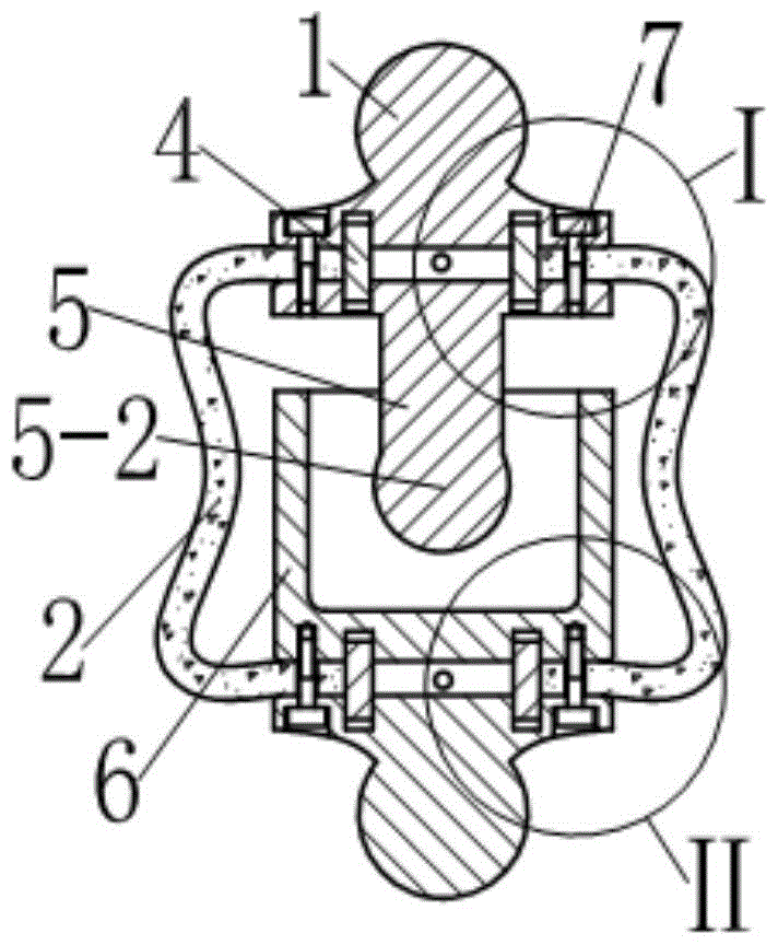
[0026] see Figure 1~6 , the joint prosthesis includes a limit rod 5, a limit sleeve 6 and an elastic cover 2 wrapped outside the two; the cross section of the limit sleeve 6 is ring-shaped, and its upper end is open, and its lower end is closed; The upper end of the limiting rod 5 is coaxially provided with a connection plate 5-1, and the lower end is provided with a ball head 5-2 with a diameter smaller than the inner diameter of the limiting sleeve 6; the lower end of the limiting rod 5 extends into the A joint structure is formed in the limiting sleeve 6 .

[0...

example 2

[0035] see Figure 8 , The difference between this example and Example 1 is that the middle part of the connecting rod 1-1 corresponding to the position of the spinous process arches away from the connecting flange 1-1 to form a curved part 1-2. The curved portion 1-2 can provide better movement space for the spinous process inserted between the two connecting rods 1, and can better preserve the function of the spinous process and nearby tissues after the operation.

[0036] Embodiments other than the above in this example are the same as Example 1.


PUM


Abstract

The invention discloses an artificial lumbar facet joint system, which comprises two connecting rods and two joint prostheses, wherein the two connecting rods span over vertebral pedicles on two sides of a same lumbar vertebra bone and the two joint prostheses are clamped between the two connecting rods; each of the joint prostheses comprises a limiting rod, a limiting sleeve and an elastic cover which covers outside the limiting rod and the limiting sleeve; a connecting tray, which is coaxial with the limiting rod, is arranged at the upper end of each of the limiting rods, and the lower end of the limiting rod extends into the limiting sleeve from an opening of the limiting sleeve, so that a joint structure is formed by the limiting rod and the limiting sleeve; two ends of the elastic cover extend towards the centers of two ends of the joint structure in a radial direction, and two ends of the elastic cover are fixed to two ends of the joint structure by virtue of locating rings; on each of two sides of spinous process of lumbar vertebra, a connecting flange is arranged on each of the connecting rods; and the two joint prostheses are clamped in the two pairs of connecting flanges on two sides of the spinous process of lumbar vertebra. The artificial lumbar facet joint system disclosed by the invention can reconstruct functions of a lumbar facet joint after excision and can reserve normal tissues around the facet joint to the greatest extent.

Description

technical field [0001] The present invention relates to a prosthesis for the spine which can be implanted in the body, which is suitable for reconstructing facet joint function after lumbar decompression surgery. Background technique [0002] On either side of each vertebra in the lumbar spine, there are a pair of upward facet joints, called the superior facets, and a pair of downward facets, called the inferior facets. The positions of a pair of superior articular processes and a pair of inferior articular processes between adjacent vertebral bodies correspond to each other to form facet joints, and there is a pair of facet joints between every two adjacent vertebrae. Because the facet joints are relatively small, they are also called facet joints in the spine. The facet joints form the back wall of the intervertebral foramen, and the nerve roots of the neck and waist pass through the front of the facet joints. Therefore, when the facet joints degenerate and hyperplasia an...

Claims


Application Information

Patent Timeline
Patent Type & Authority Patents(China)
IPC IPC(8): A61F2/44
CPCA61F2/44
Inventor 付茂庆欧阳钧孙培栋
Owner SOUTHERN MEDICAL UNIVERSITY
Why Eureka
Try Eureka