Sliding rail type mechanical stirrer

A stirrer, mechanical technology, applied in the direction of mixer accessories, mixers with rotating stirring devices, chemical/physical/physicochemical stationary reactors, etc., can solve shaft vibration, noise, deflection, inconvenient motor adjustment, Long stirring time and other problems, to achieve the effect of reducing the amount of vibration, the number of parts used, and sufficient stirring

Inactive Publication Date: 2016-06-29
JILIN UNIV
View PDF3 Cites 7 Cited by
  • Summary
  • Abstract
  • Description
  • Claims
  • Application Information

AI Technical Summary

Problems solved by technology

[0008] The invention provides a simple structure, using a symmetrical slide rail motor adjustment part to solve the problems of inconvenient motor adjustment and working vibration; using a shaft reinforcement to solve problems such as shaft vibration, noise, and deflection; Disadvantages of tight brackets; the use of a liftable base solves the problem of insufficient stirring due to the fixed position of the stirring impeller; the use of a new type of stirring impeller solves the problems of insufficient stirring and low circulation, and solves the problem of gas-liquid by adding a small fan wheel The problem of long stirring time of the reaction; a slide-type mechanical stirrer that uses a simple splash-proof cover to solve the problem of splashing of the stirred liquid during the stirring liquid

Method used


Image

  • Sliding rail type mechanical stirrer
  • Sliding rail type mechanical stirrer
  • Sliding rail type mechanical stirrer

Examples


Embodiment Construction

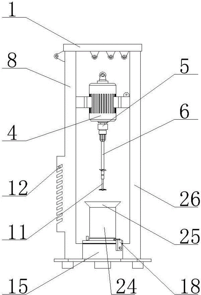
[0035] refer to figure 1 , a slide rail type mechanical stirrer, the stirrer includes a motor adjustment part, a stirring part, a base part and a stirring container part, wherein the motor adjusting part is fixed at both ends of the base part; the stirring container part Adsorbed on the base part; the upper end of the motor adjustment part is connected with the stirring part through a steel wire rope, and the two ends are closely matched with the stirring part.

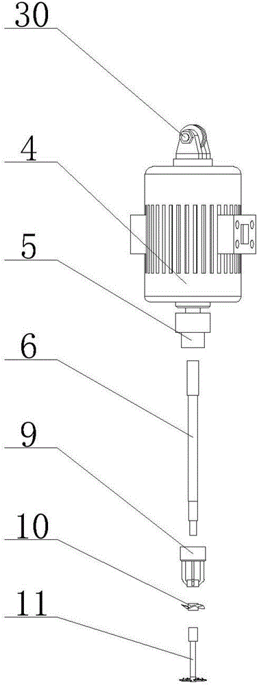
[0036] refer to figure 2 , Figure 7 , Figure 8 , Figure 11 , the motor adjustment part includes pillar cover 1, slider a2, pulley a3, runner block d7, slide rail a8, snap rod 12, snap slot 13, slide rail b26, slider b27, pulley b28, pass Hole 29, wheel block c31, wheel block b32 and wheel block a33;

[0037] The slider b27 and the slider a2 are in the shape of "T", the lower end of the "T" of the slider b27 is installed with a pulley b28 stuck in the inner track of the slide rail a8, and the lower end of the ...


PUM


Abstract

The invention discloses a sliding rail type mechanical stirrer which comprises a motor adjustment component, a stirring component, a base component and a stirring container component, wherein the motor adjustment component is fixed on the base component; the stirring container component is adsorbed on the base component; and the upper end of the motor adjustment component is connected with the stirring component through a steel wire rope, and two ends are matched with the stirring component in a separate tightening manner. According to the sliding rail type mechanical stirrer, by the adoption of symmetric sliding rail motor adjustment, the problems of inconvenience in motor adjustment and working vibration are solved; by the adoption of a shaft reinforcement piece, the problems of shaft vibration, noise, and deflection are solved; by the adoption of a magnet adsorption type base, the problem that a stirring trough clamps a bracket is solved; by the adoption of a lifting type base, the problem of poor stirring due to a fixed position of a stirring impeller is solved; by the adoption of the stirring impeller, the problems of poor stirring and small circulating amount are solved; by the additional arrangement of a fan wheel, the problem of long stirring time in gas-liquid reaction is solved; and by the adoption of a simple anti-splashing cover, the problem that a stirred liquid is splashed to a user in a liquid stirring process is solved.

Description

technical field [0001] The invention belongs to a stirring device, in particular to a slide rail type mechanical stirrer for laboratories. Background technique [0002] The laboratory mechanical stirrer is generally composed of two parts: a stirring vessel and a stirrer; the stirring vessel includes a stirring tank, clamping parts, etc.; the stirrer includes a motor, a stirring shaft, and a stirring impeller. [0003] In the prior art, the motor is generally fastened to a support column with bolts and nuts through an external clamping device, and the height of the motor is selected by manually adjusting its tightness. When it is used, it is easy to cause the shaking of the support column and affect the stirring effect; for example, in the patent CN105413520A "A New Type of Laboratory Stirrer", the invented new type of laboratory stirrer is asymmetrical in appearance, which may cause connection during work. The board vibrates unstable. [0004] In the prior art, the power o...

Claims


Application Information

Patent Timeline
Patent Type & Authority Applications(China)
IPC IPC(8): B01J10/00B01J19/18B01F7/18B01F15/00
CPCB01J10/00B01J19/0066B01J19/18B01F27/213B01F27/806B01F27/90B01F35/3214B01F35/413B01F35/43B01F35/3204B01F2101/2204
Inventor 陈书明贾纪昭张继修王登峰陈静郭晗井晓瑞
Owner JILIN UNIV
Why Eureka
Try Eureka