Traction and straightening mechanism on reinforcement hoop bending machine

A straightening mechanism and hoop bending machine technology, which is applied in the field of traction and straightening mechanisms, can solve the problems of steel bar 800 flattening, support bearing damage, crushing, etc., and achieve the effects of stable work, low noise and convenient installation

Active Publication Date: 2016-06-29
TJK MACHINERY TIANJIN
View PDF6 Cites 7 Cited by
  • Summary
  • Abstract
  • Description
  • Claims
  • Application Information

AI Technical Summary

Problems solved by technology

[0005] like Figure 5 , Image 6 As shown, the reason why the two steel bars 800 slip under the processing mode is due to the deviation of the diameter of the steel bars 800 itself, the existence of ribs of the ribbed steel bars, etc. Reinforcing bar 800 often is one is compressed, and another one is not fully compressed, and during processing reinforcing bar 800, just be just between the reinforcing bar 800 that is not fully compressed and power wheel 2062, compacting wheel 2061 (gauge length wheel 2061a). There will be skid phenomenon, if adopt to strengthen the compression force of compression wheel 2061 (meter wheel 2061a) to prevent the skid between steel bar 800 and power wheel 2062, can reduce skid phenomenon really, but this method can cause steel bar again 800 is crushed, and the phenomenon of crushing occurs, and excessively pressing the pressing wheel 2061 (the length measuring wheel 2061a) will cause the pressing wheel 2061 (the length measuring wheel 2061a), the power wheel 2062 and the support bearing etc. to move too fast damage

Method used


Image

  • Traction and straightening mechanism on reinforcement hoop bending machine
  • Traction and straightening mechanism on reinforcement hoop bending machine
  • Traction and straightening mechanism on reinforcement hoop bending machine

Examples


Embodiment Construction

[0024] In order to further understand the invention content, characteristics and effects of the present invention, the following examples are given, and detailed descriptions are as follows in conjunction with the accompanying drawings:

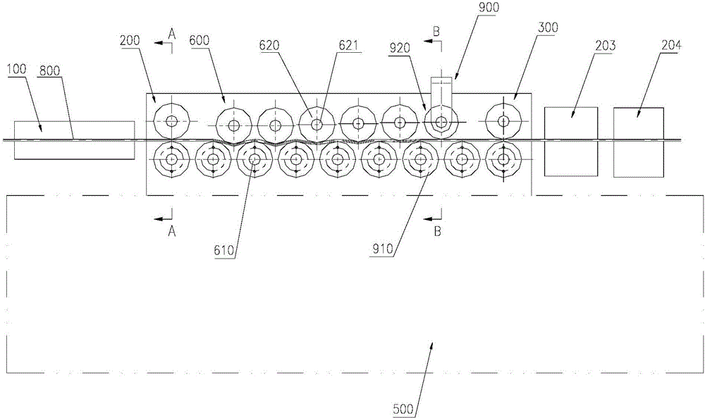
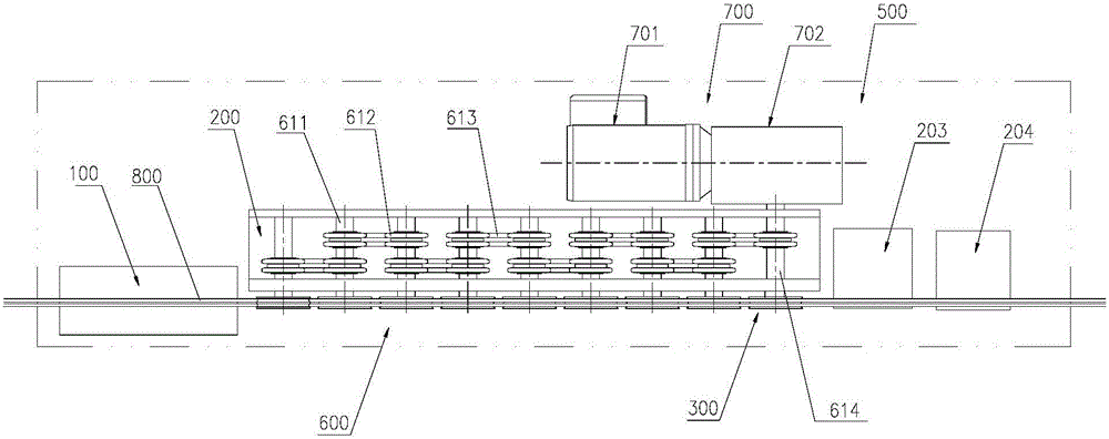
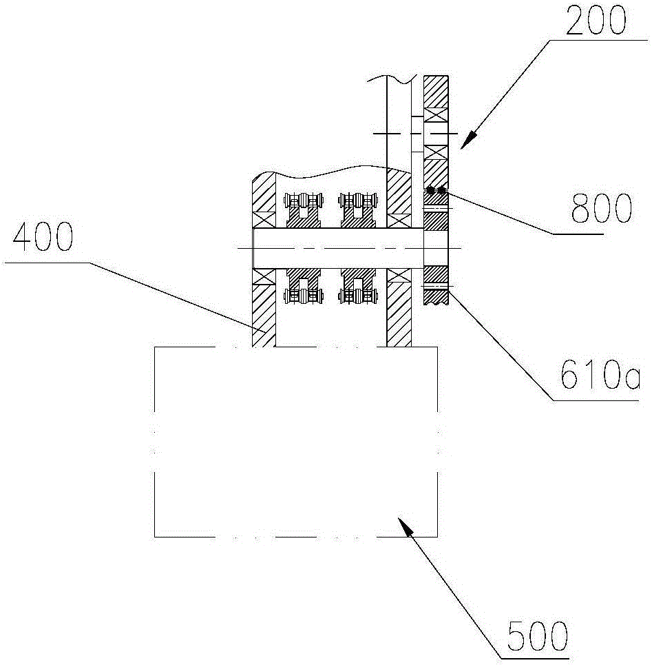
[0025] see Figure 1 to Figure 4 , a traction and straightening mechanism on a steel bar hoop bending machine, comprising a traction wheel set 200 and a traction meter long wheel set 300; the traction straightening mechanism between the traction wheel set and the traction meter long wheel set On the casing 400, the traction wheel set 200 and the long wheel set 300 of the traction meter all adopt a pair of opposing pressure wheel sets to facilitate the traction of the steel bar; the traction straightening box 400 is installed above the frame 500, and At least one set of longitudinal traction straightening mechanisms 600 is arranged between the group 200 and the traction meter long wheel set 300, and each set of longitudinal traction straighten...


PUM


Abstract

The invention relates to a traction and straightening mechanism on a reinforcement hoop bending machine. The mechanism comprises a traction wheel set and a traction length counting wheel set; a set of longitudinal traction and straightening mechanisms is at least arranged between the traction wheel set and the traction length counting wheel set; each set of longitudinal traction and straightening mechanisms at least includes two driving wheels and one driven wheel; the driven wheel is staggered from the driving wheels; the driving wheels are mounted on a traction and straightening box through driving shafts; transmission wheels are mounted on the driving shafts in the traction and straightening box; transmission components are assembled on the transmission wheels, and are connected with driving devices; the driven wheel is mounted on the traction and straightening box through a driven shaft; and straightened reinforcements are matched and pressed between the driven wheel and the driving wheels. The mechanism is convenient to penetrate and tow the reinforcements through arrangement of pressing wheels, and effectively tows the reinforcements during straightening the reinforcements through arrangement of staggered wheels to prevent slippage, so that the surface quality of the reinforcements is improved, and the efficiency is improved; and in addition, the mechanism has such advantages as simple structure, convenience for installation, stable work, low noise and energy consumption saving.

Description

technical field [0001] The invention belongs to the technical field of steel bar hoop bending machine equipment, and in particular relates to a traction and straightening mechanism on a steel bar hoop bending machine. Background technique [0002] The automatic steel bar bending machine is an automatic processing equipment that bends steel bars into different shapes of hoops. The automatic steel bar bending machine is widely used in urban construction, transportation construction and other fields. The traction mechanism of the double-line steel bar bending machine in the prior art relies on two compression wheels to press the steel bar on the power wheel, and relies on the friction between the steel bar and the power wheel to feed the material. When the mechanism processes the steel bar, the gap between the steel bar and the power wheel It is very easy to slip between the steel bars and the power wheel, and the slipping will scratch the steel bar and the power wheel, causing...

Claims


Application Information

Patent Timeline
Patent Type & Authority Applications(China)
IPC IPC(8): B21F1/02B21F23/00B21C51/00
CPCB21C51/00B21F1/02B21F23/00
Inventor 陈振东
Owner TJK MACHINERY TIANJIN
Why Eureka
Try Eureka