Numerical control winging head used for engraving machine

A technology of engraving machine and swinging head, which is applied in the field of numerical control swinging head, can solve the problems of not improving work efficiency, low processing efficiency, high consumption, etc., and achieve the effect of fast back and forth operation, optimization of work effect and improvement of work efficiency

Inactive Publication Date: 2016-06-29
扬州旺海数控设备科技有限公司
View PDF0 Cites 1 Cited by
  • Summary
  • Abstract
  • Description
  • Claims
  • Application Information

AI Technical Summary

Problems solved by technology

[0002] Engraving machines are widely used in the engraving industry, especially when engraving large-area layouts, it is necessary to use engraving machines with CNC swing heads. Such engraving machines can process a wide range and high processing precision, but At present, when many engraving machines are in use, it is often difficult to ensure the lubrication of the track of the CNC swing head. Sometimes the track is not smooth enough, which affects the back and forth operation of the CNC swing head, and the processing efficiency is not high. There are also some CNC swing heads. The head is lifted and lowered by the belt. This working lifting mode will lead to inaccurate positioning, and the lifting and lowering of the CNC swing head is not timely. It consumes more when lifting and lowering, and the work efficiency cannot be improved.

Method used


Image

  • Numerical control winging head used for engraving machine

Examples


Embodiment Construction

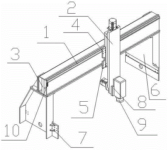
[0010] The present invention will be further described below in conjunction with the accompanying drawings.

[0011] A numerically controlled swing head for engraving machines, including a guide rail 1 and a numerically controlled swing head 2, the guide rail 1 is a strip-shaped structure, the guide rail 1 is provided with a support 3, the support 3 is located on both sides of the track, and the support 3 is T-shaped The CNC swing head 2 is connected to the guide rail 1, and the wear-resistant part 4 is arranged between the CNC swing head 2 and the guide rail 1. The wear-resistant part 4 is a copper wear-resistant part, and the wear-resistant part 4 is located at the On the side, the wear-resistant part 4 is connected with the numerical control swing head through threads, and the wear-resistant part 4 is provided with a clamping port 5, which is in the shape of a semicircle, and a support frame 6 is provided under the guide rail 1, and the support frame 6 is in the shape of a t...


PUM


Abstract

Disclosed is a numerical control winging head used for an engraving machine. The numerical control winging head comprises a guide rail and a numerical control winging head body. The guide rail is of a long-strip-shaped structure and provided with support parts. The support parts are located on the two sides of the guide rail and of a T-shaped structure. The numerical control winging head body is connected beside the guide rail. An abrasion-resistance part is arranged between the numerical control winging head body and the guide rail and made of copper. The abrasion-resistance part is located on the side edge of the numerical control winging head body and connected with the numerical control winging head body through threads. The abrasion-resistance part is provided with a clamping opening which is in the semicircular arc shape. The guide rail is provided with a lubricating part capable of lubricating the guide rail in time, so that the sliding effect of the numerical control winging head body on the guide rail is ensured, back-and-forth operation can be conducted fast, and the work effect of the engraving machine is improved. A hydraulic lifting component is arranged outside a speed reducer so that lifting of the numerical control winging head body can be faster, the work effect of the engraving machine is optimized, the machining quality can be ensured, and locating is more accurate.

Description

technical field [0001] The invention relates to a numerically controlled swing head, in particular to a numerically controlled swing head for an engraving machine. Background technique [0002] Engraving machines are widely used in the engraving industry, especially when engraving large-area layouts, it is necessary to use engraving machines with CNC swing heads. Such engraving machines can process a wide range and high processing precision, but At present, when many engraving machines are in use, it is often difficult to ensure the lubrication of the track of the CNC swing head. Sometimes the track is not smooth enough, which affects the back and forth operation of the CNC swing head, and the processing efficiency is not high. There are also some CNC swing heads. The head is lifted and lowered by the belt. This working lifting mode will lead to inaccurate positioning. The lifting and lowering of the CNC swing head is not timely. Contents of the invention [0003] The obj...

Claims


Application Information

Patent Timeline
Patent Type & Authority Applications(China)
IPC IPC(8): B44B3/00B44B3/06
Inventor 庞小鹤
Owner 扬州旺海数控设备科技有限公司
Why Eureka
Try Eureka