Laminated scanning based phase-difference wavefront detection and image restoration method

A technology of wavefront detection and phase difference, which is applied in the direction of measuring devices, measurement optics, optical radiation measurement, etc., can solve the problem of increasing system volume, complexity and cost, affecting the restoration accuracy of phase difference algorithm, and affecting the restoration image of wavefront detection accuracy Quality and other issues, to achieve the effect of improving the wavefront detection ability

Active Publication Date: 2016-06-29
INST OF OPTICS & ELECTRONICS - CHINESE ACAD OF SCI
View PDF6 Cites 13 Cited by
  • Summary
  • Abstract
  • Description
  • Claims
  • Application Information

AI Technical Summary

Problems solved by technology

[0003] However, the current phase difference method still has many limitations: the phase difference method is essentially an image-based inversion technology, which needs to extract wavefront information and restore the image according to the collected light intensity information, which is artificially introduced as prior information The aberration of the image will inevitably cause the image to lose part of the information, thereby affecting the accuracy of wavefront detection and the quality of the restored image, and the ability of the phase difference method to detect wavefront distortion is therefore restricted; in the application field with high requirements for resolution, For example, in astronomical observation, the aperture of the imaging system needs to be made very large, and the pixel size of common CCDs is ...

Method used


Image

  • Laminated scanning based phase-difference wavefront detection and image restoration method
  • Laminated scanning based phase-difference wavefront detection and image restoration method
  • Laminated scanning based phase-difference wavefront detection and image restoration method

Examples


Embodiment

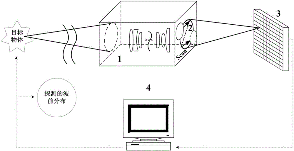
[0046] The optical system based on the new method of wavefront detection and image restoration of the present invention is composed of an imaging system 1, a spatial modulation unit 2, an image sensor 3 and a computer 4. The working principle of the whole system is as follows figure 1 Shown:

[0047] Its specific working process is:

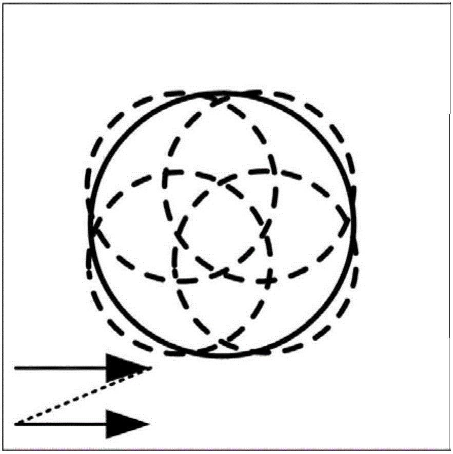
[0048] (1) Translating the small-aperture diaphragm in the pupil plane of the imaging system 1 in a stacked scanning manner. stack scan as figure 2 As shown in Fig. 1 , the small-aperture diaphragm used for scanning is sequentially translated by a certain distance in the two-dimensional pupil plane to complete the modulation, and to ensure that there is a certain overlap in the area scanned by the diaphragm on the pupil plane between adjacent translation positions. The stack scanning is completed by the spatial modulation unit 2, which can be a mechanical mobile platform, or a fast modulation device such as a digital micromirror device (Digita...


PUM


Abstract

The invention relates to a laminated scanning based phase-difference wavefront detection and image restoration method which can be used for restoring wavefront distortions and capable of effectively restoring blurred images affected by aberrations. According to the method, a small-aperture diaphragm is moved within a pupil plane of an imaging system in a laminated scanning mode, and corresponding sub-images affected by different aberrations are recorded by using an image sensor. The recorded series of sub-images are processed by using the laminated scanning based phase-difference wavefront detection and image restoration method, and wavefront distortions of the system can be detected and the images can be restored. The method adopts the small-aperture diaphragm to perform space scanning so as to produce the sub-images having phase differences. Compared with various existing technologies for phase difference methods, the Nyquist sampling frequency is more easily met, an aberration detection range is large, out-of-focus light paths and various diffraction devices are not needed, and the laminated scanning based phase-difference wavefront detection and image restoration method has the advantages of being compact in system, convenient to use and the like.

Description

technical field [0001] The invention relates to the technical field of wavefront detection and image restoration, in particular to a phase difference wavefront detection and image restoration method based on stack scanning. Background technique [0002] The phase difference method was first proposed by GonsalvesRA. By adding the known defocus aberration to the wavefront to be measured, according to the obtained focal plane light intensity distribution and multiple light intensity distributions located on different defocus planes, based on least squares, Using the GS algorithm can effectively detect wavefront distortion and restore blurred images contaminated by aberrations at the same time. Due to its simple structure, high measurement accuracy and no special requirements for light sources, this technology has been widely used in the fields of remote sensing and wavefront detection, and has received extensive attention and research from domestic and foreign scientific resear...

Claims


Application Information

Patent Timeline
IPC IPC(8): G01J9/00
CPCG01J9/00
Inventor 谢宗良马浩统任戈亓波史建亮崔占刚谭玉凤王智鹏何小君董理
Owner INST OF OPTICS & ELECTRONICS - CHINESE ACAD OF SCI
Why Eureka
Try Eureka